Motion Control & Motors Blog
7 Resources For Understanding Inertia and Inertia Mismatch
When sizing the most appropriate motor for a given application, factors such as load inertia and motor inertia are critical considerations. (Via: Understanding The Mysteries of Inertia Mismatch’)
If mechanical components such as couplings, shafts and belts were infinitely stiff, it would be possible to size motors based solely on torque and speed requirements. Unfortunately, this is not the case.
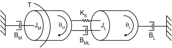
In a compliantly coupled motor and load, a number of factors influence mechanical resonances of the system, including the rotor inertia of the motor (JM), the load inertia (JL), the coupling elasticity (KS), the applied torque (T), and the viscous dampening of the coupling (BML), between gound and rotor (BM) and between ground and load (BL). Figure courtesy of Kevin Craig, Hofstra University.
Every one of these mechanical components has a degree of compliance, which means that when the motor attempts to move a load, vibrations result at resonant frequencies. Successful motor sizing requires some understanding of inertia, so let’s take a look at some key concepts.
Inertia is the resistance of any physical object to any change in its speed. As inertia increases, so too does the resistance to acceleration/deceleration. Load inertia, also referred to as the moment of inertia, is defined as the resistance of a physical object to any change to its speed, from the perspective of the rotational axis.
The moment of inertia (usually written as J) in a servo system can be divided into two parts: the load inertia and the motor inertia. The moment of inertia ratio is the load’s moment of inertia divided by the motor’s moment of inertia. Inertia mismatch refers to the difference of physical inertia between the motor and the load.
To help with motor sizing, motor makers typically provide permissible load inertia information. Exceeding the permissible load can lead to reduced performance, vibration, and stalling.
Keep in mind that there is no formula for calculating some ideal inertia ratio –it has to be calculated for every application.
High load-to-motor inertia ratios decrease the operating bandwidth of the machine, make the motor work harder than it should, and often lead to increased settling times, resulting in decreased overall performance.
One way to reduce the inertia ratio is to use gearboxes since gear ratio has an inverse square effect on the inertia of the load. This enables higher-speed operations and/or smaller and cheaper motors. Another approach is to switch to a bigger motor with larger inertia.
In addition, today’s advanced servos come with drive control algorithms that can be used to tackle resonance effects, which allows the use of higher-ratio systems for certain applications.
ROI Calculator

Discover the potential cost savings of robotic automation over a 20-year system life
This calculator compares your current manual labor costs against the total cost of owning and operating a robotic system over its 20-year lifespan.
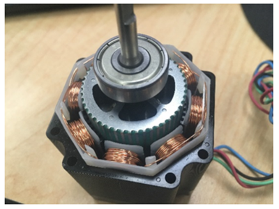
Rotor inertia can be adjusted via changes to materials, dimensions and designs (such as the ‘car-wheel’ design shown here). Credit: A3
Here are 7 useful resources for exploring inertia and inertia mismatch topics:
- Understanding The Mysteries of Inertia Mismatch: This in-depth article from the A3 archives provides a detailed breakdown of the topic, including equations. Focuses on how inertia and coupling stiffness combine to create instabilities in servo axis operation – and how this issue can be resolved.
- Servo Motor Sizing Basics: Yaskawa America’s excellent series of free, online robotics-related eLearning Modules includes this video covering core motor sizing concepts such as peak torque, RMS torque, inertia ratio, and speed.
- Robot Academy Inertia Videos: Queensland University of Technology’s free, online Robot Academy provides several videos exploring the topic of inertia in different motion control and robotics contexts.
- Motor Sizing Basics: Load Inertia: A concise guide to the topic of inertia from leading motor maker Oriental Motor.
- Destaco has provided a useful online tool designed to help you calculate inertia ratios.
- Understanding Inertia Ratio and Its Effect On Machine Performance: An excellent whitepaper from Mitsubishi Electric that explains the fundamentals of inertia ratio and the dangers of following crude rules of thumb when sizing motors.
- Solutions to Reduce Stepper Motor Resonance: Did you know that by adjusting the motor and/or changing the load inertia you can reduce stepper motor resonance? Find out more in this article from the A3 archives.
Share This On X:
If mechanical components such as couplings, shafts and belts were infinitely stiff, it would be possible to size motors based solely on torque and speed requirements. Unfortunately, this is not the case.
There is no formula for calculating some ideal inertia ratio –it has to be calculated for every application. Learn more about inertia and inertia mismatch in this blog.
Recent Posts
- Emerging Technologies Driving Modern Motion Control Systems: Five Trends Reshaping Factory Automation
- Electronic Camming: Enabling Superior Flexibility in Advanced Motion Control Systems
- Electronic Camming: Enabling Superior Flexibility in Advanced Motion Control Systems
- How Electrification is Reshaping Motion Control
- Motion Control in Harsh Environments: Engineering for Extremes
- Next-Generation Motion Control: Integrating IIoT and Real-Time Data Analytics
- View All Motion Control & Motors Blogs