Industry Insights
Motion Control Puts Ink to Paper
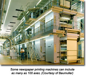
From magazines and business cards to cartons and packaging, printing is alive and well. Today’s presses move beyond paper to print text and graphics on webs of everything from tissue to plastic film. Printing machines can contain as many as 100 axes, all of which have to be precisely synchronized to maintain web tension and print registration. And to maintain that synchronization? Motion control.
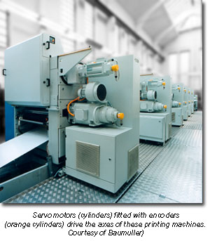
 “Modern machines use it for everything from web tension control to turning the print heads and ink rollers,” says Ray Seifert, director of applications engineering at Baumuller Inc. (Bloomfield, Connecticut). Conventional mechanical designs typically feature gearboxes connected to a master driveshaft to synchronize rollers or run them at proportional speeds. Such systems require mechanical adjustments, which take time and generally require line shutdowns for everything from changing web thickness to correcting registration. “Electronically, you can do that very easily by using a virtual electronic driveshaft that gives you synchronized motion,” says Seifert. The servo motor and stepper motor systems of motion control not only synchronize rollers, they correct print registration and speed the changeover of everything from the type of web material to the number of colors used in the design.
Tension Triumphs
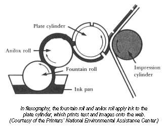
Much of today’s printing is performed using flexography, in which a flexible rubber or polymer plate carrying a positive master image is wrapped around a roller known as the plate cylinder. An additional set of rollers transfers ink from a reservoir to the plate cylinder. When the web runs between the plate cylinder and its opposing impression cylinder, the lettering and images from the flexible surface of the plate cylinder transfer to the web surface.
 In the standard four-color printing process, each color (cyan, magenta, yellow and black) is typically applied in a separate print module with its own ink reservoir, transfer rollers, plate cylinder and impression cylinder. Add to that, rollers to feed the web into the machine and maintain tension throughout the process and it’s easy to see how some newspaper printing machines can feature dozens of axes.
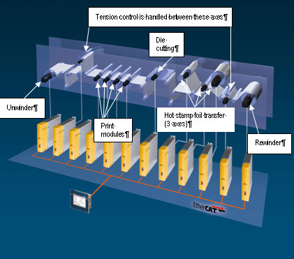
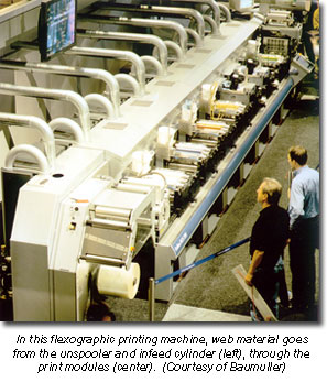
To get it all started, an infeed cylinder pulls the web from an unwinder and feeds it into the rest of the rollers of the machine. In addition to the cylinders in the print modules, others support the web and ensure that it moves smoothly. The type of light cardboard used for cereal boxes is fairly robust, but in the case of fragile materials like tissue paper and plastic film, tension control is crucial.
“Web tensioning control is a huge part of a quality print process,” says Seifert. “That also needs to be carried out through the motion control. Every 2 ms or 4 ms or whatever cyclic communication rate is chosen, your master control gives position commands to the slaves. The pinch roller in the back of the line that is actually pulling the web through the machine would run off the master command and that would run pretty much synchronously, but phasing in and out to keep the tension where it needs to be.”
“We use electronic line shafting to be synchronized to either an internally generated master signal or an external signal like an encoder that would be on an upstream machine,” says Brian Schmidt, senior applications engineer at Bosch Rexroth AG (Hoffman Estates, Illinois). “The infeed axis is synchronized to this same signal so that the speed of the rolls is correct, but then on top of that base speed there’s also going to be some correction to maintain tension.”
Although the design would seem to be best suited to a centralized control architecture, the high axes counts can instead lead to hybrid architectures of daisy-chained controllers or PLCs. “On our systems we do have a fairly distributed control concept,” says Schmidt. “Our controls can coordinate up to 64 axes on one controller but if you have a machine that is 100 axes, then you definitely need multiple controllers. Of course, there is a central point of control that ties everything together,” he adds.
Feedback for tension adjustment can come from a load cell, but a preferred solution is a pneumatic roller arm called a dancer that exerts pressure on an opposing roller on the underside of the web, and shifts position depending on whether the web is moving too rapidly or too slowly. The dancer establishes the tension by the force it exerts, while at the same time it provides feedback to the dancer control, which speeds or slows the infeed to keep the dancer steady. By balancing the force exerted by the dancer, the system both controls dancer position and indirectly controls web tension. “We add or subtract some velocity on top of the base speed in order to maintain the tension or dancer setpoint,” says Schmidt. “You can parameterize to determine how responsive the controller is going to be in terms of reacting to errors that it sees in the tension or dancer position.” The dancer can also absorb a certain amount of tension disturbance.
 Each substrate material presents different tension requirements, which means adjusting the base speed, as well as the gains on secondary control loops. Electronic shafting offers the advantage that such parameters, once established, can be stored for future retrieval. The flexibility of motion control also allows operators to move various print modules on and offline, depending on which colors they need for their design. A seemingly monochrome blue design might require cyan, magenta and black, while another might require only cyan and black. Motion control makes this changeover simple and speedy.
Flex Factors
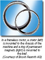
Of course, flexibility isn’t always a good thing. Backlash or sponginess introduced by the coupling of motor to load can introduce tension problems. The frameless motor approach provides one solution. Instead of a traditional motor shaft coupling to the cylinder to drive it, a ring bearing permanent magnets is attached to the cylinder. A stator mounted to the machine chassis surrounds this ring; essentially, the elements of the machine themselves become the motor.
 By eliminating the need for couplings, such designs offer greater stiffness. “Normally the coupling between the motor and the load is a limiting factor in how well we can control the servo, in that it adds a certain amount of springiness,” says Schmidt. “When we take that spring out of out of the equation, we are able to achieve much higher gains on the servo control loops. We can basically increase the gains by an order of magnitude, which results in much higher dynamic range and accuracy.”
The downside is that the frameless approach requires more effort from the OEM machine builder. They have to design the load -- in this case, the cylinder -- so that a part of it fits the rotor. The load will also require a bearing, although a conventional bearing without constraints dictated by the motor. Machine designers also need to add a feedback device, as well as a housing around the stator element. Replacing a motor is no longer as easy as unfastening four bolts and attaching a new unit. That said, the performance demands of the application may merit the extra effort.
“Direct drive motors can be applied to a print cylinder and allow us to control the surface of that cylinder to accuracy of better than a thousand of an inch,” says Schmidt. Some printing machines are designed around a common impression roll that can be as large as 10 feet in diameter. Even a small ripple in angular velocity on such a cylinder can have big repercussions, making the frameless approach a worthwhile tradeoff. “If we take the gear train and coupling out of there and put in one of these direct drive motors, we’ve improved velocity smoothness,” says Schmidt. “This roll is the surface around which the paper is wrapped as its being printed, so the more smoothness you can achieve with the speed that drum is turning, the better the print registration.”
Registration Responses
 Print registration -- synchronization of the print rolls for different colors -- is a key attribute of high quality printing. Rather than have this task performed by the main motion system, registration adjustments are typically handled by an additional motion system, such as a stepper motor system. “It’s a little lower bandwidth,” says Seifert. “You don’t need to have the high speed updates. Once you get [the machine] into registration, it just runs synchronously.” Accordingly, many machines use a different field bus to run the registration system than to synchronize the rollers. “The stepper motor is coupled into the print cylinder via a differential gearbox, so you have a master just running synchronously to give you your synchronous speed and then you’re doing the phasing with this stepper motor at a much lower speed,” he continues. “It’s just adding to the speed through this gearbox, bringing it into phase.”
Of course, printing machines perform other tasks such as cutting the finished product. There, observer control or velocity feed forward/acceleration feed forward techniques can further minimize velocity ripple. “It usually isn’t too big of a deal in constant velocity places like the print cylinder, but we have applications where we run electronic cams that have to speed up and slow down,” says Schmidt. “For instance, a rotary cutter would be a cylinder with some kind of knife or die pattern on it. We want to be able to cut a certain length of product with it. In order to do that, we run an electronic cam that will speed up or slow down that cylinder during the time that it’s not in contact with the web in order to be back around in time to make the next cut.”
Taken as a whole, motion control is bringing big benefits to printing. “Electronic shafting allows you the flexibility to add colors so that you only need to run as many axes as you need for a specific job,” says Seifert. “What the implementation of the servos has done, we’re to the point now where our flexographic printing process really rivals the offset printing processes in quality.” So the next time you’re reading the back of your Cocoa Puffs box at breakfast, know that you’ve got motion control to thank for it.
Certified Motion Control Professional Program
Strengthen Your Skills and Enhance Your Career
Become a Certified Motion Control Professional (CMCP) and join the elite group of system integrators, machine builders, manufacturers, end-users and others recognized in the industry for their professional knowledge and expertise.
Motion Control & Motor Association
The Motion Control and Motor Association (MCMA) – the most trusted resource for motion control information, education, and events – has transformed into the Association for Advancing Automation.
Discover how Motion Control & Motor Association can support your automation journey with their complete range of solutions and expertise.
Visit Company WebsiteMotion Control & Motor Association 
The Motion Control and Motor Association (MCMA) – the most trusted resource for motion control information, education, and events – has transformed into the Association for Advancing Automation.
The Lenze Smart Motor: a Single Motor for Many Applications
Lenze Americas recently introduced its innovative Smart Motor designed for applications ranging from material handling to packaging automation.
Siemens - Simotics T-1FW6 Series Torque Motors Expanded
Siemens Drive Technologies Division is adding two frame sizes to its range of built-in torque motors in the lower output range