Industry Insights
Understanding Power Factor and Harmonics
At a time when lean manufacturing has become the mantra of industry, minimizing energy costs has assumed ever greater importance. It’s not just a matter of controlling consumption, however, but of how that consumption is billed by the utility. This is where power factor plays a key role. Power factor is the ratio of real power to apparent power in an electrical system. The lower the power factor, the higher the current draw. Higher current requires thicker wires and a more robust infrastructure in order to minimize power dissipation. Because this increases cost to utiliies, facilities with low power factors get charged a higher rate. Fortunately, techniques exist to correct power factor and harmonics. In this tutorial, we’ll take a closer look at these concepts as they apply to servo motors and drives.
Power factor provides a measure of the efficiency of an electrical system. True power factor consists of two terms: displacement power factor and total harmonic distortion. It is frequently simplified to just displacement power factor, but that only holds for a specific class of linear loads. Servo drives and variable-frequency drives are nonlinear loads, so the simplification no longer applies.
Let’s consider displacement power factor first, starting with some definitions:
- Real power (P), in units of watts (W), is the power dissipated by the load. This is the power used to generate torque in the motor.
- Reactive power (Q), in units of volt-amperes reactive (VAR) is power stored and discharged by the inductive and capacitive components of the system. This is the power that generates the magnetic flux that causes the motor to turn.
- Apparent power (S), in units of volt-amperes (VA), is the vector sum of the real power and the reactive power.
Using these terms, we can define the displacement power factor PFD by:

where δ1 is the phase angle of the voltage, θ1 is the phase angle of the current; we refer to φ as the power factor angle.1 Power factor is a dimensionless number that ranges from -1 to 1. A low power factor indicates that the reactive load is consuming a larger portion of the total current; a negative power factor indicates that the load is generating current.
We can show the relationships among real, apparent and reactive power in vector space in what is commonly called the power triangle (see figure 1):

For a purely resistive load, the voltage and current are in phase. The power-factor angle is zero and the power factor becomes unity. For purely inductive or capacitive loads, real power reduces to zero and the power factor falls to zero, also. In the case of a real inductive load like a motor, the voltage leads the current, increasing the power-factor angle to yield a displacement power factor of less than one.
A low displacement power factor indicates a system that is not using power effectively. Using equation 1, we can express real power as:

Decreasing PFD increases P. Of course, P = IV, and for a fixed voltage, current has to rise to compensate for a low displacement power factor. Increased current introduces larger resistive losses, which forces the utility to install oversized wires and transformers to push the same amount of power. This leads to the rate increase we discussed above.
For linear, purely sinusoidal loads like fixed-speed motors running pumps and fans, displacement power factor correction is fairly straightforward. Capacitive reactance can cancel inductive reactance. Although the voltage phase leads the current phase for inductive loads, current leads voltage for capacitive loads. As a result, we can improve power factor simply by adding capacitors. Unfortunately, servo motors aren’t linear loads, which means we have to find a different solution.
True power factor
Servo drives and variable-frequency drives (VFDs) use diode-bridge rectifiers. Diodes only conduct for the part of the cycle when the input voltage is higher than the DC bus voltage, which introduces harmonics that distort the power signal. At the controller, everything will look fine, with a displacement power factor of around 0.95. The numbers don’t tell the whole story, however. If you measure total current times voltage in the system and calculate true power factor (PFT), it will be low.
As we mentioned above, true power factor consists of more than just displacement power factor. It’s actually expressed as the product of displacement power factor and distortion power factor:
PFT = PFD x DPF
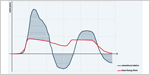
The distortion power factor term is introduced by the harmonics. A closer look at the signal will show that the current waveform is no longer a 60-hertz sine wave. The harmonics introduce high-frequency content that converts it into a double-hump pattern (see figure 2).2
, introduced by high harmonic content. It is fed by a power system with an impedance of 104 µH in series with 39.2 mO. The drive has an RMS input current of 10.6 A (red) and an RMS AC current in the DC bus capacitors of 10.4 A (blue). Note, although this plot is for an AC drive, servo drives behave similarly. (Courtesy of Schneider Electric)")
ROI Calculator

Discover the potential cost savings of robotic automation over a 20-year system life
This calculator compares your current manual labor costs against the total cost of owning and operating a robotic system over its 20-year lifespan.
The distortion power factor is given by:

where THD is total current harmonic distortion (for a full derivation, see reference 1).
A servo system typically generates fifth- and seventh-order harmonics at high magnitudes, as well as contributions from higher-frequency terms. (We are ignoring the third-order term in this case because, for a three-phase system, the third-order harmonic at 180 Hz cancels out when it goes through the rectifier.)
Any time a servo axis is moving, it’s generating harmonics and contributing to the problem. Unfortunately, because the load is nonlinear, it cannot be corrected by a linear load in the form of a power-factor correction capacitor. We must look for other solutions. Linking drives on a shared DC bus can mitigate the problem somewhat. If accelerating axes are harvesting current from decelerating axes, they’re not drawing from the mainline.
Another approach to handling harmonics is to add an inductance, like a line reactor or a DC choke. Let’s take a look at the drive from figure 2, now fed by a power system with a much lower impedance. Exposing DC bus capacitors to current spikes can cause a high degree of heating, changing the expected lifetime from years to days (see figure 3).
 shows that the peak input current has changed to a series of high, narrow spikes (green). The RMS input current has jumped to 16.3 A (red) and the RMS AC current in the DC bus capacitors has grown to 18 A (blue). (Courtesy of Schneider Electric).")
If we add a 3% line reactor, the performance changes (see figure 4). The addition of inductor impedance dwarfs the impedance of the input power system, so the spikes are both lower and broader, like the system driven as rated in figure 2. The line reactor also protects the input diodes from voltage spikes on the line.
. The RMS input current reduces to 6.1 A (red) and the current in the DC bus capacitors drops to 2.8 A (blue). (Courtesy of Schneider Electric).")
A line reactor is not the only approach. An equivalent DC choke can be used instead to yield a slightly better waveform. Unlike an AC line reactor, the DC choke does not go to zero at the reversal points, which has the effect of smoothing the hump profile (see figure 5). It does not provide as much protection to the input diodes, however.
. The change drops the RMS input current to 6.0 A (red) and the current in the DC bus capacitors to 2.0 A (blue). (Courtesy of Schneider Electric)")
When it comes to running a servo-based system, displacement power factor alone is not a useful assessment of performance. It is essential to analyze and address the effects of harmonics on the system or else you may be faced with unanticipated faults or subpar performance on a regular basis. Ideally, each drive would have either an input line reactor or a DC choke, but this is not typically standard equipment. It will need to be designed in by the panel builder.
Of course, as in all things in engineering, there is no one correct solution. For best results, analyze your system performance and open a dialogue with your vendor to ensure you achieve the performance and reliability that you expect.
Acknowledgments
Thanks to James Crook, senior staff engineer at Schneider Electric for helpful conversations.
References
- W. Grady and R. Gilleskie, “Harmonics And How They Relate To Power Factor,” Proc. of the EPRI Power Quality Issues & Opportunities Conference (PQA’93), San Diego, CA (1993).
- “The Effects of Available Short-Circuit Current on AC Drives,” Schneider Electric technical bulletin (2008).
Did you like this content? See it in person at Automate.
Motion Control & Motor Association
The Motion Control and Motor Association (MCMA) – the most trusted resource for motion control information, education, and events – has transformed into the Association for Advancing Automation.
Discover how Motion Control & Motor Association can support your automation journey with their complete range of solutions and expertise.
Visit Company WebsiteMotion Control & Motor Association 
The Motion Control and Motor Association (MCMA) – the most trusted resource for motion control information, education, and events – has transformed into the Association for Advancing Automation.
What You Need to Know About the New Motor Efficiency Standards
Permanent-magnet motors have increasing roles to play in continuous-duty applications.
Cut Energy Costs Using Motion Control
Developing an energy-efficient servo system can save you as much as 30% on your operating costs.
Advanced Motion Controls Releases µZ Servo Drives
Weighing only 8.5 grams and capable of outputting 10A peak and 5A continuous µZ’s are the smallest off-the-shelf servo drives