Motion Control & Motors Blog
How to Weld Non-Standard Parts Using Automation
Custom, non-standard parts once caused challenges for welding systems. But there are best practices for the robotic welding of non-traditional parts.
Understanding what makes the part non-standard, off-line programming, and using 3-D measuring devices are among the successful approaches used in this type of flexible automation.
Knowing Non-Standard Parts
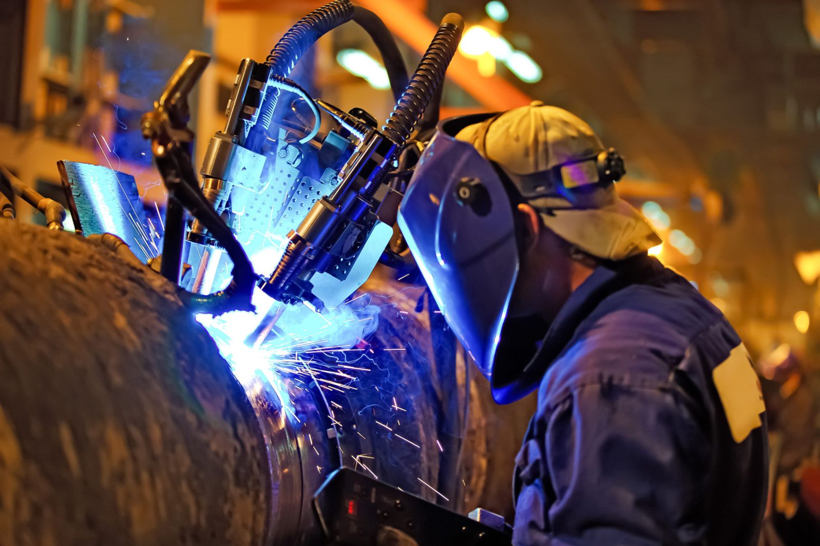
In the webinar, there is a photo of an augur joint with a circular shape and uneven join lines that makes automated welding a challenge. The welding tip has to be lined up and kept on point. Another image shows a FANUC robot welding a wind turbine.
Part consistency was once essential for robotic welding success, but the development of sophisticated software and vision systems make flexible welding a realistic solution.
Non-standard parts have varying shapes, sizes, and can come in different types of materials and many times are produced in small quantities which can mean frequent programming changes. There are steps to take that keep the process manageable and affordable.
Handling Non-Standard Welds
A three-person panel on the webinar addressed approaches to handling unusual welding requirements. Dan Hasley of Cenit, says a first step is to check the robot’s “reachability and accessibility” to the part. Cenit, a RIA member, produces FASTSTUITE, a product family to support digital manufacturing. The use of 3-D programming software checks the tool path prior to production.
Doing test welds is an important first step according to Steve Spanjers, Triton Innovation, a systems integrator that focuses on advanced data collection built into the equipment. He says testing will “validate the simulation” while checking on heat distortion and how the material will move.
ROI Calculator

Discover the potential cost savings of robotic automation over a 20-year system life
This calculator compares your current manual labor costs against the total cost of owning and operating a robotic system over its 20-year lifespan.
Jerry Wright of Genesis Systems says his team does a 3-D simulation of the part and tests equipment in an automated solution center. He will also do 3-D printing of the parts to help determine the best tooling options. Genesis Systems is an integrator certified through A3’s Certified Integrator program.
Setting Up a Non-Standard Cell
Changing from one type of welding to a robotic solution and setting up a welding cell is covered in the article Flexibility in Automation on the website Welding and Design Fabrication.
A customer replaced atomic hydrogen welding with powder feed plasma overlay welding using robots from ABB and it’s shown in a detailed diagram.
Infrared welding is another option used to weld plastic parts in the automotive industry.
The cameras, combined with an analysis done by software, recognizes when a temperature is within the upper and lower control limits. When the weld is within acceptable limits then an approval signal is sent via the programmable logic controller and the weld continues.
If the software “fails” the part then the welding stops.
Automation is a field of cross-disciplines that’s bringing industry together with academic researchers and vocational skills centers. Stay up to date on the trends that impact your company with the many free resources available through A3.
Recent Posts
- Emerging Technologies Driving Modern Motion Control Systems: Five Trends Reshaping Factory Automation
- Electronic Camming: Enabling Superior Flexibility in Advanced Motion Control Systems
- Electronic Camming: Enabling Superior Flexibility in Advanced Motion Control Systems
- How Electrification is Reshaping Motion Control
- Motion Control in Harsh Environments: Engineering for Extremes
- Next-Generation Motion Control: Integrating IIoT and Real-Time Data Analytics
- View All Motion Control & Motors Blogs