Tech Papers
EtherCAT Digital Control Bus Primer
ETHERCAT PRIMER
1. EtherCAT – What is it?
Over the years there has been a need for an open low-cost digital control bus for automation and motion control. Some were available but had proprietary technology. With the introduction of EtherCAT it has become the accepted open standard for Ethernet-based control buses.
EtherCAT was designed specifically for deterministic control of industrial peripheral devices including but not limited to servo and stepper drives, I/O modules, sensors, and encoders. Basically, any EtherCAT device can be connected to a given network. Being an open technology, EtherCAT can handle multiple functions using multiple protocols depending on the system architecture. For the purposes of this paper we will focus on the use of EtherCAT running CoE (CanOpen over EtherCAT) protocol in closed-loop motion and I/O control systems. Other EtherCAT protocols are also mentioned.
EtherCAT has been gaining more and more acceptance by vendors of automation and control components as the bus of choice. Among the reasons are performance, versatility and ease of implementation. At this writing there exist over 80 I/O venders, 110 different drive vendors (slaves) and over 150 master controllers available. EtherCAT has also become the accepted standard in the semi-conductor industry making it the most adopted and implemented industrial control network
EtherCAT technology overcomes the system limitations of other Ethernet solutions. That is, the Ethernet data packet is no longer received, then interpreted and copied as process data at every connection. Instead, the Ethernet frame [telegram] is processed on-the-fly by the newly developed FMMU (fieldbus memory management unit) in each slave node which reads the data addressed to it while the telegram is forwarded to the next device. The frames are only delayed by a fraction of a microsecond in each node, and many nodes can be addressed with just one frame.
2. Implementation
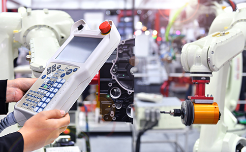
The traditional closed loop servo system consists of the analogue command and encoder position feedback of 10 or more wires plus drive enable. For high axis count systems the individual connections can add up. Performance is good in the analogue system but there are short comings. There is no ability to read or write drive parameter information. The motion controller and drive are two separate units in the system. Resolution of the system is typically 12-16bit for the command, and encoder pulse count is often a trade-off with motor speed due to frequency limitation.
As system resolution demands increase and higher axis-count systems become more common place the need for a smarter interface between motion/machine controller and servo drives was needed. EtherCAT fills that need by providing a simple, flexible inexpensive digital interface for a variety of peripherals including drive and I/O control.
Traditional 3-axis analogue servo system requires at least 10 wires per axis.
EtherCAT brings some distinct advantages to the servo control system:
- Replaces the analogue velocity or torque command to a servo drive, encoder position feedback, and drive enable with a single Cat5e cable.
- Much higher system resolutions are achievable in velocity commanded systems - 32bit vs. 12-16bit speed reference.
- Wiring cost is greatly reduced and simplified. Easily expandable.
- The master controller can read and write parametric data to the drives making a more versatile and integrated system.
- Drive parameters can be sent at power up by the master simplifying configuration and replacement.
- Transparent to the user – An EtherCAT system runs the same as an analogue system from a user program standpoint.
EtherCAT devices can be connected in line, star or tree topology. The most common in motion control system is the line configuration, also referred to as daisy chained shown below. In this configuration no additional Ethernet switches are needed keeping system cost low. A tree configuration can easily be created using standard EtherCAT devices, or a star configuration using a special EtherCAT supported switch to handle the telegram packet transfer. Regardless of the physical topology, there is a single EtherCAT telegram which is forwarded around the entire network on one 'logical' path. The master controller will find the slaves in order on this path, and automatically assign them an address based on their position on this path through the network. Alternatively, a slave device can be set a particular node address via hardware switches.
The most common EtherCAT configuration used in motion control is the “Line” connection
Since 100Base-T Ethernet physical layer is used, the distance between any two nodes can be up to 100m. If an EtherCAT network is wired in a ring configuration (requires two ports on the master device), it can provide cable redundancy. In most systems this redundancy is typically not used or needed. An EtherCAT master can be implemented in software on a PC or embedded controller using any standard Ethernet MAC.
For slave devices an EtherCAT Slave Controller (ESC) is required in order to perform the "processing on the fly" principle. This is typically implemented using an FPGA, ASIC or microprocessor. In the commonly used line configuration the last slave in the chain will close an open port automatically and return the Ethernet frame if no downstream device is detected. Slave devices typically have two ports but may have only one, designed to sit at the end of a network.
EtherCAT overcomes the non-deterministic nature of standard Ethernet TCP/IP using a Distributed Clock (DC) technique. This enables an EtherCAT network to provide the precise time synchronisation between the master and slaves in order to guarantee deterministic operation required for coordinated motion control. The distributed clock technique leads to a very low jitter, of significantly less than 1µs, between the synchronised master and slaves even if the communication cycle jitters. The typical process of establishing a distributed clock is initiated by the master sending a broadcast to all slaves to a certain address. Upon reception of this message, all slaves will latch the value of their internal clock twice, once when the message is received and once when it returns. The master can then read all latched values and calculates the delay for each slave. This process can be repeated as many times as required to reduce jitter and average out values. Total delays are calculated for each slave depending on their position in the slave-ring and will be uploaded to an offset register. Finally, the master issues a broadcast read/write on the system clock.
In some systems the first slave is the reference clock forcing all other slaves to set their internal clock appropriately with the now known offset. Other stand-alone EtherCAT masters such as Trio’s MC4x series initiate and maintain the reference clock.
2.1. The EtherCAT Telegram
A simplified Ethernet frame containing EtherCAT data is shown below. The EtherCAT protocol uses an officially assigned EtherType of 0x88A4 inside the Ethernet Frame. When a slave device receives the Ethernet frame it first looks at the EtherType to determine if it should process the data. Otherwise the packet is sent off and nothing is done. The advantage of the unique EtherType allows transport of control data directly within the Ethernet frame without redefining the standard Ethernet frame.
A typical telegram used for closed-loop motion control will contain several datagrams, one for each command being sent. The number of datagrams will vary based on the functions being performed. The length of the datagrams shall vary depending upon the number of slave nodes in the system (a slave node for our purposes is defined as a servo drive, remote I/O module, or encoder).
Specific commands are sent by the master for closed-loop motion control. These include a distributed system clock, process data objects (PDOs), and a mailbox for service channel type data.
Each datagram begins with a 10-byte header that contains a specific EtherCAT command. Any required data for that command then follows. A working counter (WKC) terminates each datagram. The WKC enables the master to monitor the number of successful memory transactions which occurred while the telegram was passed around the network, and also allows the master to detect missing nodes on the network.
In our example, the distributed clock (DC) is the first datagram command. The DC synchronises all the slaves to the master as previously mentioned. The next datagram is the logical read/write (LRW) command used for writing a new command position and reading back actual position from a servo drive. The third datagram of the motion control telegram is the mailbox. The mailbox in the telegram is a mechanism to read or write asynchronous data with any node on the network. A user program running in the master may want to request data from a slave. In a servo drive, for example this might be motor torque or bus voltage. Since the EtherCAT protocol for motion is based on the CiA402 CanOpen standard any valid object in the slave’s dictionary can be used to exchange data with the master.
Certified Motion Control Professional Program
Strengthen Your Skills and Enhance Your Career
Become a Certified Motion Control Professional (CMCP) and join the elite group of system integrators, machine builders, manufacturers, end-users and others recognized in the industry for their professional knowledge and expertise.
2.2. Initialising the Network
Before the EtherCAT network can operate it must first be initialised. The network is initialised by the master either automatically at power up or under user control by going through a series of four states.
Prior to network initialisation the master requires parameters to identify and configure the slaves. The manufacturer for the slave device provides an ESI (EtherCAT Slave Information) data file for this purpose. The ESI file is loaded into the master controller before the run up process in the majority of masters. The Trio MC4x series maintain a library of pre-loaded ESI parameters for many commonly used slaves to facilitate automatic configuration, considerably simplifying the commissioning of a new network.
At power up, the master first enters the Initialise (Init) state to identify all the slave devices on the network. In the Init state, low level mailboxes are configured for data exchange within the ESC slave chip. After successful completion of the Init state, the Pre-Op state is entered which gains access to the mailboxes and sets up the slave's CoE objects. The third state is Safe-Op and the master begins cyclic data transfer including I/O data. The transfer rate is the servo period as defined by the particular master.
The final state is Operational which puts the slaves into full run mode.
A system initialise example is shown below with configuration output printed to a terminal window from a Trio MC4x EtherCAT master. Here the controller identifies a system with network I/O at node 0 and several vendor drives at nodes 0-5.
>>
EtherCAT State: Init (0)
EtherCAT State: Pre-Operational (0)
EtherCAT State: Safe-Operational (0)
EtherCAT State: Operational (0)
EtherCAT Configuration (0):
750-354: 0 : 3 : 1003 (24:16/24:16/0:0/0:0) + (0)
SD RS2: 1 : 0 : 1 (1)
SGDV: 2 : 0 : 2 (2)
AKD: 3 : 0 : 3 (3)
AMC: 4 : 0 : 4 (5)
AMC: 5 : 0 : 5 (6)
>>
3. Performance
EtherCAT lends itself well to short cycle times since the main microprocessors in the slave devices are not involved in the processing of the Ethernet packets to transfer the process images. Process data communication is handled in the slave ESC chip hardware with very low propagation delays (< 1µs). Because of this very small latency and high bandwidth utilization, EtherCAT boasts some impressive numbers. It is possible to address 100 servo axes (each with 8bytes in + out) in 100µs, and 1000 digital I/O points can in 30µs. Of course, other factors may limit system performance.
The typical EtherCAT motion control system has a cyclic update rate of 1-5kHz, with most in the 1-2kHz range. The update rate, which is also the servo period, is set by the master and generally does not need to be changed, although is a user settable parameter in the master.
Because EtherCAT is a fully digital interface, high position resolution is achievable. The protocol is based on sending and receiving 32bit position commands resulting in a max position of 4,294,967,296 counts. Many servo drives support feedback resolution of 220 providing up to 1,048,576 counts per motor revolution. High speed frequency limitations such as systems with traditional quadrature encoders are not an issue being in the digital domain.
Systems with very high axis counts and more complex motion such as gearing, camming, and interpolation, may find the update rate needs to be adjusted. This is to accommodate the increased telegram size and calculations overhead required by the master.
4. Protocols
EtherCAT is built on the standard IEEE 802.3 Ethernet frame, and can support several protocols simultaneously. These include; CanOpen over EtherCAT (CoE), File over EtherCAT (FoE), Safety over EtherCAT (FSoE), Servo (Sercos) over EtherCAT (SoE), and Ethernet over EtherCAT (EoE). Although the EtherCAT Specification defines all these protocols, a slave shall implement only those necessary for its successful operation.
4.1. CoE - CanOpen over EtherCAT
Developed by the CAN In Automation (CiA) group, CoE includes the underlying CanOpen Application Layer and Communication Profile (CiA 301) and several device profiles, including CanOpen Profile for Drives and Motion Control (CiA 402).
CoE is the primary protocol used in EtherCAT control systems, taking advantage of the well-defined CanOpen specification for cyclic motion control. Adapting the protocol to run over EtherCAT was straight forward for many vendors already familiar with CanOpen. Standard CanOpen objects are used to exchange data with slave devices.
4.2. FoE – File over EtherCAT
File over EtherCAT allows file transfers with devices such as servo drives. This can be used for uploading firmware or similar files from the master to slaves.
4.3. FSoE – Fail-Safe over EtherCAT
The datagrams outlined for motion carry what is considered ‘non-safe’ information. That is, the data received and executed at the slave is not validated between devices. FSoE, otherwise known as Functional Safety over EtherCAT, defines a safety communication layer, or “black channel” for the transportation of safety process data between supporting FSoE devices. FSoE meets the requirements of IEC 61508 Safety Integrity Level (SIL) 3 and enables the transfer of safe and standard information on the same communication system without limitations with regard to transfer speed and cycle time.
Safety over EtherCAT uses a master/slave relationship between two FSoE devices. It is ensured that each device only returns its own new message once a new and valid message has been received. The complete transfer path between master and slave is thus monitored in each cycle. This enables very lean implementation of the protocol, with moderate requirements in terms of communication system access, since no hard timings for time synchronization is needed.
The EtherCAT master does not have to be the Safety master which means that certified FSoE devices can be added to any suitably enabled EtherCAT network without the EtherCAT master itself requiring certification.
4.4. SoE – Servo (Sercos) over EtherCAT
SoE protocol employs a Sercos like standard over EtherCAT particularly for motion control applications. Access to all parameters and functions residing in the drive is based on the EtherCAT mailbox. Like CanOpen the focus is on compatibility with the existing protocol (access to value, attribute, name, units etc. of the IDNs). Few masters support SoE since there are few drive and peripheral slave options as compared to the much more popular CoE protocol.
4.5. EoE – Ethernet over EtherCAT
EtherCAT technology is fully Ethernet compatible. There is no restriction on the type of Ethernet device that can be connected to an EtherCAT network via an EtherCAT switch port. The Ethernet frames are tunneled via the EtherCAT protocol, which is the standard approach for internet applications. The EtherCAT network is fully transparent for the Ethernet device, and the real-time characteristics are not impaired.
5. Conclusion
EtherCAT continues to gain more and more acceptance by vendors of automation and control components as the digital bus of choice with the highest adoption and implementation rate of any industrial control network. Advantages include; highest performance by processing the Ethernet frame on-the-fly, lower installation costs by eliminating the need for switches, and simplified connection between master and slave devices using standard shielded Ethernet cabling. Additionally, nodes are easily added to an existing system to increase axis count and system I/O.
Add to that file transfer (FoE) and safety (FSoE), and EtherCAT offers the flexibility to address the needs of the machine and motion control market now and well into the future. Users will be the ultimate beneficiary from the large array of devices available as more venders adopt EtherCAT.
Trio Motion Technology
Trio Motion Technology is a specialized source of high performance motion control technology, a field of automation, encompassing the systems involved in moving parts of machines, robots or motors in a precise and controlled manner. The main components involved typically include a motion controller, drives and motors or actuators.
Discover how Trio Motion Technology can support your automation journey with their complete range of solutions and expertise.
Visit Company Website
Trio Motion Technology is a specialized source of high performance motion control technology, a field of automation, encompassing the systems involved in moving parts of machines, robots or motors in a precise and controlled manner. The main components involved typically include a motion controller, drives and motors or actuators.

TwinCAT IoT Communicator Provides Secure Transfer of Process Data to Mobile Devices
Beckhoff app for tablets and smartphones uses TLS encryption and MQTT protocol to enable easy mobile device integration.
Yaskawa Releases the Z1000U HVAC Matrix Drive
Matrix Technology Provides Harmonic Mitigation, Power Factor Control, and Energy Savings in a Single Compact Package.