Editorials
Automatic Calibration of Tool Center Points
In many robot applications, such as dispensing or welding, the tool is constantly changing due to wear or deformation. As these applications often rely on the highest possible accuracy, it is necessary to regularly check and calibrate the tool center point (TCP) of the tool, e.g. after a tool change, after each maintenance, at the beginning of a work shift or even after each process cycle.
The recalibration should occur automatically. This minimizes downtime, reduces scrap and rework, and increases the quality of the produced products.
TCP Laser Calibration
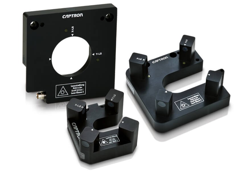
CAPTRON TCP measurement technology for industrial robots ensures maximum precision for tool calibration with a reproducibility of 0.01 mm and reliably detects both metallic and non-metallic objects.
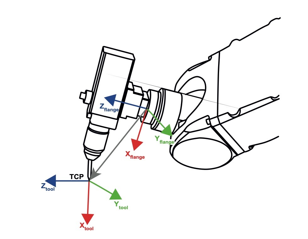
The TCP is defined relative to the robot‘s flange (see figure 1). The tool coordinates can be entered either directly numerically or measured with a calibration method. When programm- ing an application, the tool ́s coordinate system should be used. If the tool changes, the TCP is now simply adjusted to apply this change to all of the robot‘s motion programs where this tool is used.
How to Use a TCP
The instruments work with two perpendicular aligned laser light barriers to determine the robot’s tool deviations. The switching signals from the TCP measuring instrument can be used to automatically correct the TCP and thus for automatic movement correction of the robot.
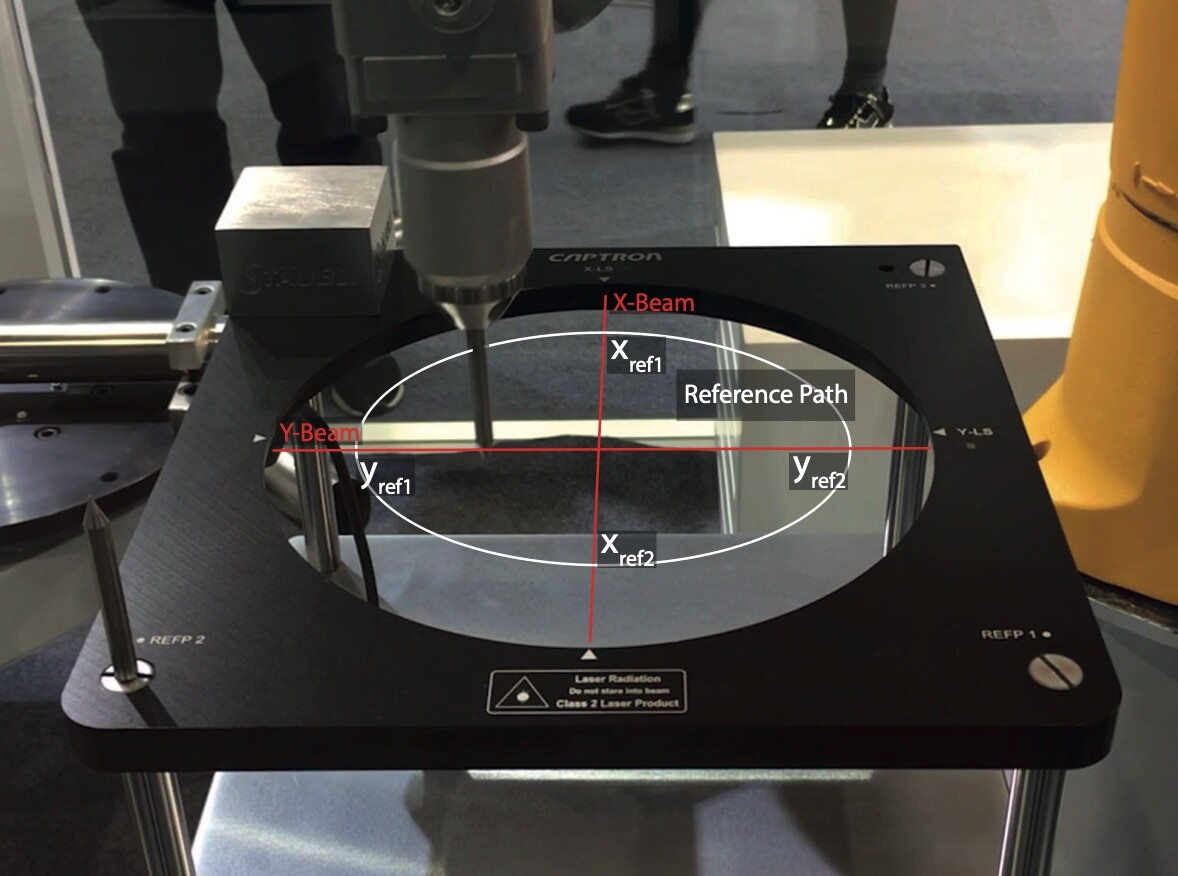
Since the tool has a diameter greater than zero, the laser beam is interrupted for the travel of the tool diameter through the laser beam. The “center” of the light interruption resulting from the falling and rising edge of the light signal of the TCP measuring instrument is the desired tool reference point xref and yref.
It is recommended to move the robot arm on a circular (or square) horizontal path within the TCP measuring device and to interrupt each laser beam twice, thus storing a total of each two reference positions in x- and y-direction (see figure 2). In this way, the calibration accuracy can be increased by means of averaging. It is also possible to determine the center point of the TCP measuring device where both laser beams cross. At this center point, it can be checked whether the re-calibration was correct since both laser beams are interrupted at the same time.
Subsequently, the motion sequences of the robot application are programmed, and the work of the robot is carried out. For recalibration, the tool is moved again on the circular path through the laser beams of the TCP measuring instrument. The deviation from the reference positions is detected and the tool is corrected accordingly in x- and y-direction.
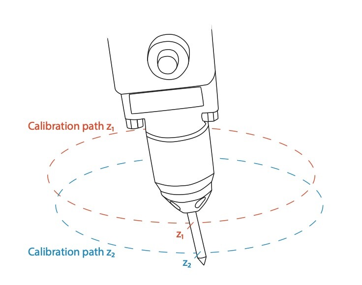
To correct a tilted tool, e.g., a bent welding tip, the robot calibration runs are performed by two circular movements at different heights z1 and z2, see figure 3. Each interruption of the x- and y- laser beams results in a correction position xcal1 and xcal2 and ycal1 and ycal2. The tilt angle α can now be calculated and corrected through the TCP deviations between the two recalibration paths.
CAPTRON ENTERS THE UR+ ECOSYSTEM

ROI Calculator

Discover the potential cost savings of robotic automation over a 20-year system life
This calculator compares your current manual labor costs against the total cost of owning and operating a robotic system over its 20-year lifespan.
CAPTRON recently announced its partnership with Universal Robots. As a UR+ partner, CAPTRON facilitates the use of CAPTRON TCP measurement technology with UR (Universal Robots).
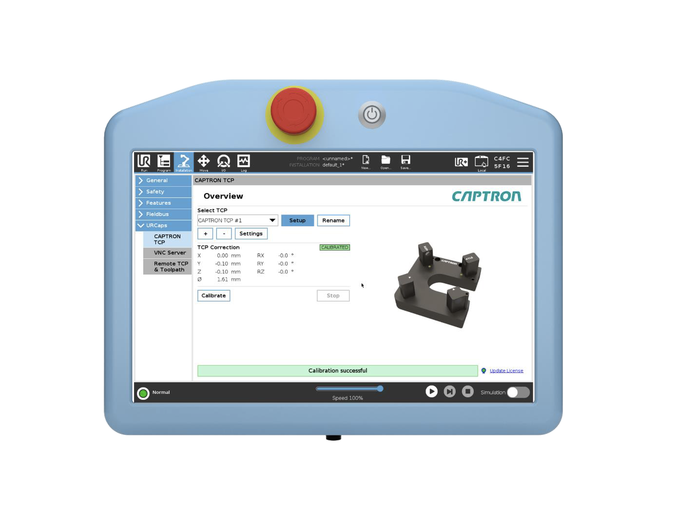
The URCap CAPTRON TCP is a software extension for the UR robot. It was developed to integrate the CAPTRON TCP sensors with minimal effort. With the CAPTRON TCP sensors, a TCP set up on the robot can be checked and adjusted during program runtime. Inaccuracies in the TCP, e.g. due to the replacement of an adhesive nozzle, can be easily corrected manually or automatically.
The URCap software is compatible with all UR e-Series (UR3e, UR5e and UR10e) robots and UR20 / UR30 with Polyscope, from version 5.11.
Being a part of the UR+ Ecosystem means that CAPTRON's system has been tested and certified by UR. We are one team working together for growth and customer success, assisting businesses of all sizes on their journey to automation.
The URCap in use
The URCap includes the following services:
- An installation page for tool calibrations with step-by-step setup of up to 10 different TCPs (measurement of X-Y-Z reference values and tool tip diameter)
- Automatic TCP recalibration can be started manually by the operator via the installation page
- A program node for automatic checking and recalibration of a TCP in a running program, limit values and speeds can be defined
- The program node can be used to check, validate or recalibrate the TCP, with or without adjusting the orientation of the robot arm
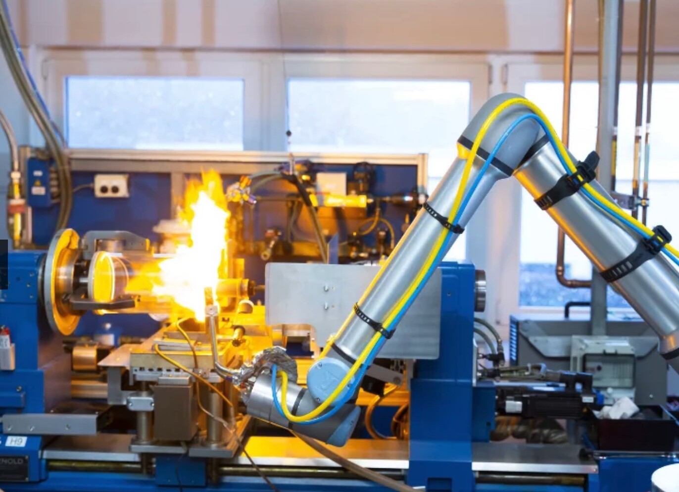
Applications
TCP monitoring and calibration is important for complex tasks that require precision and repeatability, like dispensing, welding, dosing, gluing, pipetting, soldering, drilling, and milling. When using different tools, the URCap allows for fast and precise checking of each tool.
Benefits of automatic recalibration
There are many benefits to automatic recalibration.
- Minimization of downtimes An automatic control and calibration process reduces production interruptions.
- Increasing accuracy and quality Regular inspection and calibration of the TCP ensures that robot applications are always carried out with the highest precision.
- Reduction of rejects and rework Accurate calibration minimizes errors, collisions and deviations in the production process, resulting in less scrap and rework.
- Reliable tool change After each tool change, the robot can run through a quick calibration routine to ensure that the tool has been inserted correctly and properly.
- Unrivaled speed The quick check and calibration of the TCP saves time after tool changes or when using different workstations with one cobot.
Are you looking to automate TCP calibration of a cobot? Reach out to us about our products and the integration into your processes at [email protected].
Captron North America LP
Our customers have been placing their trust in the quality and reliability of our products since 1983. From simple buttons to sophisticated systems, our products make people's everyday lives easier.
Discover how Captron North America LP can support your automation journey with their complete range of solutions and expertise.
Visit Company WebsiteOur customers have been placing their trust in the quality and reliability of our products since 1983. From simple buttons to sophisticated systems, our products make people's everyday lives easier.
10 Industrial Robot Companies That Lead the Industry
Some people feel more comfortable choosing an industry-leading brand.

Machine Vision Drives New Inroads into Electric Vehicle Manufacture
From a consumer standpoint, the emergence of electric vehicles (EVs) two decades ago changed the automotive landscape forever.