
Quantum Devices, Inc. Product

Member Since 2015
Quantum Devices, Inc. is a USA based manufacture of the QPhase optical incremental encoders. The QPhase series offers line counts up to 20,000 ppr and sinusoidal outputs. Rounding out the QPhase series is the QM35 and QML35 our new low profile, high performance modular encoders
Product filed under:
Encoders / Resolvers / Tachometers and Sensors & Feedback Devices Encoders / Resolvers / Tachometers and Sensors & Feedback Devices
QR12 optical encoder delivers improved feedback over modular encoders in a sub-one-inch package. Its bearing design boosts performance, with quadrature incremental outputs, index pulse, and three-phase commutation. A spring steel flex mount accommodates greater shaft runout and enables 30° commutation
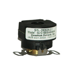
QR12 Optical Encoder Design Features:
- Low profile assembled height of less than 1″
- Bearing design simplifies encoder attachment
- Incremental resolutions up to 20,000 lines per revolution
- SIN/COS outputs available up to 1250 PPR
- 4, 6, 8, 10, 12, 14, 16, 18, 20, 36 or 60 pole commutation (others upon request)
- 1.280″, 1.575″, 1.812″ bolt circle mounting
- Through shaft sizes up to 0.375” (10 mm) diameter
- High noise immunity
- Cost competitive with modular encoders
- 500 kHz frequency response
- RoHS construction
QR12 Optical Encoder Incremental Electrical Specifications (Output Options A & B)
| Input Voltage | 5 VDC ± 5% |
|---|---|
| Input Current Requirements | 65 mA typical, 100 mA max plus interface loads |
| Input Ripple | 2% peak to peak @ 5 VDC |
| Output Circuits | A = 26C31 line driver (RS-422 or single-ended TTL) B = ABZ 26C31 line driver, UVW open collector (no U’ V’ W’) |
| Incremental Output Format | Quadrature with A leading B for CW rotation Index Pulse true over A and B High |
| Frequency Response | 500 kHz |
| Symmetry | 180° electrical ± 10% typical |
| Minimum Edge Separation | <4000 PPR = 54° electrical ≥4000 PPR = 45° electrical |
| Commutation Format | Three phase 4, 6, 8, 10, 12, 14, 16, 18, 20, 36, 60 poles (other pole counts upon request) |
| Commutation Accuracy | ± 1° mechanical |
QR12 Optical Encoder Sin/Cos Electrical Specifications (C & D Output Options)
| Input Voltage | 5 VDC ± 5% |
|---|---|
| Input Current Requirements | 65 mA typical, 100 mA max plus interface loads |
| Input Ripple | 2% peak to peak @ 5 VDC |
| Output Circuits | C = sine/cosine 1 Vpp (measured differentially), index**, UVW 26C31 line driver (RS-422 or single-ended TTL) D = sine/cosine 1 Vpp (measured differentially), index**, UVW open collector (no U’ V’ W’) |
| Incremental Output Format | Quadrature sine/cosine with sine leading cosine for CW rotation. Ungated index pulse. |
| Frequency Response | 500 kHz |
| Sine/Cosine Amplitude | 1 Vpp ± 5% (measured differentially) |
| Index Amplitude ** | C = 1 Vpp ± 5% (measured differentially) square wave D = 1 Vpp ± 5% (measured differentially) sinusoidal |
| Commutation Format | Three phase 4, 6, 8, 10, 12, 14, 16, 18, 20, 36, 60 poles (other pole counts upon request) |
| Commutation Accuracy | ± 1° mechanical |
| Z channel to U channel | ± 1° mechanical |
QR12 Optical Encoder Environmental Specifications
| Storage Temperature | -40 to 125°C |
|---|---|
| Operating Temperature | -20 to 115°C |
| IP Rating | IP40 |
| Humidity | 90% non-condensing |
| Vibration | 20 g's @ 50 to 500 CPS |
| Shock | 50 g's @ 11 ms duration |
QR12 Optical Encoder Mechanical Specifications
| Bore Diameter (Tolerance) | 0.125", 0.1875", 0.250", 0.3125", 0.375", 3 mm, 4 mm, 5 mm, 6 mm, 7 mm, 8 mm, 10 mm (+0.0006/-0.0000") |
|---|---|
| Recommended Shaft Engagement | 0.500” minimum |
| Allowable Shaft Runout | 0.007" TIR |
| Axial Shaft Movement | ± 0.030" |
| Maximum Shaft Speed | 8000 RPM |
| Interface Connector | Connector: JAE P/N FI-W15P-HFE |
| Mounting | 1.280”, 1.575”, 1.812” bolt circle (suggested hardware #6-32 button head screws) |
| Moment of Inertia | 9.1E-5 oz·in·s² |
| Acceleration | 1.0E5 radians/s² |
| Accuracy | Instrument error 1.5 arc minutes max |
Download Spec Sheet
Other Products from Quantum Devices, Inc.
.png)
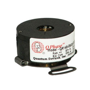
QR145 Series Incremental Encoders
QR145 optical incremental encoder provides an improved feedback solution in applications typically using modular encoders. Common options include 5-26V operation and IP66 sealed design.