Industry Insights
Resolvers Track Motion in Harsh Environments
Simple construction and analog design produce accurate, dependable feedback for high-reliability systems.
 A motion system may have the best components in the world, but without feedback, it will never be able to provide the accuracy, repeatability, and resolution typically required by motion control applications. For a number of years, optical and magnetic encoders have been the go-to solution for position feedback, but they are not effective for all situations. Particularly in the case of harsh environments or high-reliability applications, the resolver may provide a better option.
Resolvers are designed as rotary position sensors, able to monitor a motor or actuator shaft for angular position, direction, and speed. They are analog devices with no onboard electronics, which makes them both simple and robust.
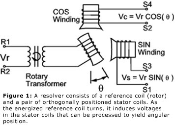
The basic design consists of a reference coil (rotor) coupled to the shaft being monitored and a pair of stationary stator coils positioned orthogonal to one another and designated as the sine and cosine coils (see figure 1). The rotor coil may be coupled to the moving shaft via brushes or, more commonly, inductively coupled across an air gap. We can think of an inductively-coupled or brushless design as a rotating transformer.
If we excite the rotor coil with an AC reference voltage Vr given by:
 = V[0] sin W[r]t](/userAssets/Image/Jan31_12_formula1.jpg)
where wr is excitation frequency , the reference voltage inductively couples to the stator coils. This induces the corresponding sine and cosine voltages Vs(t) and Vc(t), respectively:
 = K V[r](t) sin 0\ = k V[0] sin W[r]t sin0\](/userAssets/Image/Jan31_12_formula2.jpg)

where k is the transformation ratio of output voltage to input voltage and q represents the angle of the rotor with respect to the home position. We can solve for q as:
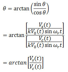
In other words, solving for the angular position is as simple as taking the arctangent of the two voltages generated by the stators.
Because a resolver is an analog device, it theoretically offers infinite resolution, as well as highly linear performance. That said, for practical purposes, the analog signal needs to be converted to a digital output in order to extract position information. Thus, the resolution of a resolver is actually driven by the resolution of the analog-to-digital (A/D) converter in the interrogator, typically amounting to a few arc minutes, although performance can be improved by techniques like oversampling.
The basic resolver design provides absolute angular position for an input shaft over 360° of rotation. Although this is a powerful characteristic, it is limited. For longer runs of travel, including motion systems with linear actuators, a resolver can be combined with a gear train that introduces a reduction ratio so that a single rotation of the resolver shaft corresponds to multiple turns of the shaft being monitored. Of course, the selection of low or zero backlash gears is essential for best accuracy.
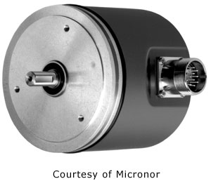
Alternately, two resolvers can be combined together in a master-slave configuration to provide an absolute sensor capable of measuring over a range of several hundred turns. In a configuration for 128 turns, for example, one resolver would have the gear wheel on it with 127 teeth and the other would have 128 teeth - one resolver tends to lag, phase wise, from the other. By reading the position of both sensors, the system can determine which turn and what position in the turn the shaft occupies; after 128 turns, they both return to zero. “With this configuration, I can tell you the shaft is at 27.555 turns," says Robert Rickenbach, President and Founder of Micronor Inc. “They're super accurate and they don't need to be referenced except once at the very beginning because they are naturally truly absolute within one turn. There's almost nothing as elegant as the master-slave resolver set up for keeping track of multi-turn position.”
Resolvers, especially brushless resolvers, can be extremely robust. The design is fairly simplistic, consisting of wire, bearings, lubricant, and a housing. With the proper choice of materials, a resolver can tolerate extreme and challenging environments that include wide temperature swings, contamination, and shock and vibration. “There is hardly anything that can influence the magnetic coupling," says Rickenbach. “As long as the bearings hold up, the resolver will not fail.”
Although the devices include conductors, they can still operate effectively at relatively high levels of EMI. The AC signal used to excite the rotor typically ranges from 2 kHz to 10 kHz, and it does not vary throughout the system. In other words, if we excite the rotor with a 5 kHz reference signal, the output signal from the stators does not alter in frequency, only in amplitude. As a result, applying a narrowband filter can remove most of the interference without affecting the results of the device.
Resolvers tend to work best when located within 100 ft of the controller. To maximize distance, designers need to take care to avoid coupling EMI or electrostatic discharge into the electronics, choosing the appropriate shielded cabling and filtering the signal as required. These approaches can be used to maximize run but they do add cost, which may be a problem for certain applications.
Selecting a resolver with the proper transformation ratio is also important. Typical transformation ratios range from 0.1 to 1.0 with most common values being 0.5 and 1. The design engineer needs to consider input signal voltage, distance and cabling loss so that the rotor input and stator output signals are of sufficient amplitude to ensure proper signal-to-noise ration and accurate A/D conversion.
Resolvers can be extremely successful in the right application but not for all uses. The devices involve a large amount of metal, so they're not a good fit for applications sensitive to mass and inertia. The costs, too, can be high, although that often stems from accessories like the six shielded wires involved rather than the resolver itself.
 Pitfalls
According to Dennis Horwitz, Technical Sales Manager at Micronor, one common pitfall is mixing up the wiring for the stators. Although there is a color code convention followed by most resolver manufacturers, there are exceptions. Users need to be sure to properly identify the sine (S1and S3) and cosine (S2 and S4) leads to avoid problems. If the wiring on the sine stator is flipped during installation, for example, it will reverse the polarity of the signal, causing the resolver to return data indicating movement in the opposite direction of the mechanical motion. To correct electrically for direction, simply reverse the S1 and S3 sine leads.
When it comes to resolvers, users have a range of choices. In addition to the shafted resolvers we've been discussing, there are frameless resolvers, which are delivered as a separate rotor and stator. The rotor is mounted on the shaft of the component being monitored and the stators are mounted on the housing. The challenges include proper mechanical alignment to minimize run out, choosing epoxies that are compatible with environmental conditions, and selecting the right type of mount. Frameless versions tend to be integrated into OEM components like motors and engines, rather than in the design of a printing machine or packaging line, for example.
System integrators wanting to include a few resolvers in their design are probably best served by purchasing a standard shafted design rather than developing their own from scratch. Such components can be customized by the manufacturer for a given environment with the choice of cabling, bearings, lubricant, and housing, freeing the systems integrator to get the best possible performance without having to deal with the intricacies and mechanical finesse of mounting a resolver.
The fact that a resolver is part of an integrated system presents an additional challenge. It's not enough to simply properly specify the resolver, it has to be coupled to the device under test so that the resolver is isolated from external stresses. “Mounting a rotational sensor is an art," says Rickenbach. "People may pick a resolver that is highly accurate but then couple it to the machine and put a high load on the bearing by mechanically not positioning it properly, by not using a flexible coupling. Initially it works, but instead of lasting for 10 years and beyond, it breaks after a year."
When it comes to position feedback, design teams have a variety of choices ranging from absolute and incremental optical and magnetic encoders, to fiber-optic encoders to resolvers. As with most things in motion control, there is no one right answer. "For each type of sensor, there's an application where one makes more sense than the others," says Horwitz. "But if the sensor is going to be mounted in a harsh environment, then that's where the resolver is likely to go."
Motion Control & Motor Association
The Motion Control and Motor Association (MCMA) – the most trusted resource for motion control information, education, and events – has transformed into the Association for Advancing Automation.
Discover how Motion Control & Motor Association can support your automation journey with their complete range of solutions and expertise.
Visit Company WebsiteMotion Control & Motor Association 
The Motion Control and Motor Association (MCMA) – the most trusted resource for motion control information, education, and events – has transformed into the Association for Advancing Automation.
Biography for Peter Diamandis, X Prize Foundation
Biography for Peter Diamandis, X Prize Foundation
Lenze OEM Business Development Team Manager to Discuss Centralized and Decentralized Drive Options
Tom Jensen of Lenze Americas will present a Manufacturing/Packaging track session entitled Centralized or Decentralized: Application–Specific Drive Strategies at 3
With Smart MechatroniX, Bosch Rexroth offers new solutions for the Factory of the Future
The first mechatronic solution packages are already available or are in the test phase