Tech Papers
Understanding Line Scan Applications
Benefits of line scan cameras including perfect, high resolution images, and the ability to image large objects.
A line scan camera has a single line of pixels that image across an object. To build up a two-dimensional image of the object, either the camera or object is moved perpendicular to the line of pixels. This might seem like a complicated way to image an object compared with “frame cameras” that take two-dimensional images (a “frame”). However, when the object is large, continuously moving, or the task needs perfect or high resolution imaging, a line scan camera is often a much better choice than a frame camera.
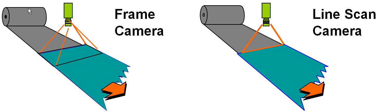 Suppose a machine vision system is to inspect long rolls of material, such as paper or plastic, for defects. A resolution of 16,000 pixels across the material is needed to detect these defects. The material is unrolled under the camera and the material’s speed is measured by a rotary encoder connected to the unrolling mechanism.
You could use four large-format frame cameras mounted across the web of material, but this has disadvantages.
First, large-format frame cameras usually have defective pixels that can hide the defects you are trying to detect. Second, the frame camera’s exposure time must be short to prevent blurring due to the material’s motion. A short exposure requires high intensity lighting over the entire imaged area to get an acceptable image. Third, optically aligning the four cameras is difficult. Last, removing offset and gain variations in pixel responses – necessary to detect low contrast defects – is time consuming with frame cameras.
A single, 16,000 pixel line scan camera is a much better solution. One camera now spans across the material and with no defective pixels. A motion encoder triggers the acquisition of each line of the image. Line exposure time is short to avoid motion blur, but now the illumination can be focused into a line, rather than being spread out over a frame. If more sensitivity is needed, Time Delay and Integration (TDI) line scan cameras (discussed below) can be used. Last, the gain and offset of each pixel is corrected in the camera to give a uniform response over the line of pixels.
When to Use Line Scan Technology
Line scan technology is ideally suited to applications in which large, high-resolution, high-speed image capture is needed, such as continuous web applications such as paper, textiles, metal, or glass inspection. Line scan technology is required for tasks, such as inspection of flat panel displays, solar cells, or printed circuit boards that must have large, defect-free images.
Line scan cameras are better than frame cameras when the product speed is high, because you can compensate for short exposure times by using concentrated illumination or use a Time Delay and Integration (TDI) camera to increase the photons “harvested”. A line scan camera computes gain and offset correction in the camera, while an frame camera uses the vision system’s CPU to compute this correction and so is slower.
How Line Scan Images are Formed
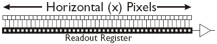
A line scan sensor has one or more lines of pixel sensors. During the camera’s exposure time each pixel accumulates photoelectric charges proportional to the light from the object imaged onto that pixel. At the end of the exposure time the charges in an entire row of pixels are transferred into a readout register. The readout register shifts out the pixel charges and they are amplified, corrected and digitized to produce the camera output. The readout register shifting is done while the next row of pixels is being exposed. The maximum rate at which exposure and readout can occur is called the “line rate” and is specified in kilohertz (kHz). To “freeze” the motion of fast moving objects, high line rates are needed. Teledyne DALSA line scan cameras have line rates of up to 200 kHz, or 5 microseconds per line of pixels imaged.
Line Scan Acquisition Interfaces
The pixel data from the camera are transmitted to a vision processor or to a frame grabber for processing. Teledyne DALSA provides cameras with three types of data transmission interfaces. Gigabit Ethernet (GigE) can sustain data rates up to about 80 Megabytes per second (MB/s). CameraLink interfaces use a frame grabber to receive the data, in “full format” can transmit up to 680 MB/s. The HSLink interface transmits 6000 MB/s to a frame grabber. The frame grabber or vision processor accumulates the transmitted lines of pixel values into a frame – an image with the width (X dimension) of the line scan sensor and a user-specified height. Frames are processed to perform machine vision tasks, as examples, finding defects or reading text (OCR). Successive frames are overlapped in the vision processor, to detect features or defects that span two frames.
Time Delay and Integration
Time Delay and Integration (TDI) line scan cameras have 2 to 256 rows of pixels, arranged vertically. Photoelectrons from each pixel in each row are summed into the row of pixels “below”, in synchrony with the product motion. The shifting and summing is driven by the object’s movement rate, usually signaled by pulses from a motion encoder. TDI cameras effectively multiply the exposure time by the number of rows of pixels and so can provide high-contrast images even when exposure time is short.
Color Line Scan Cameras
Color line scan cameras have rows of sensor pixels with different color filters to detect light of different wavelengths.Typically filters are what we perceive as red, green, and blue (RGB), but some applications use different filter types. Color line scan cameras are often used for inspecting printed products. The different colored rows are aligned by the camera. You must use a lens with low chromatic aberration and it is best to have the camera view perpendicular to the product’s surface.
Lighting for Line Scan Cameras
Line scan cameras typically use a “line light”, focused light from a line of LEDs, to illuminate the object along the line of object pixels being viewed. Line lights give high intensity illumination needed for short exposure times (fast camera line rates). Line lights can be “butted” together to give very long lights for viewing wide objects.
Selecting the Right Line Scan Camera for Your Application
Here are important considerations when choosing a line scan camera:
Sensitivity
“Sensitivity” asks, “Is the camera getting enough photons to perform the machine vision task?” It is usually difficult to answer this question only from component specifications. In practice we estimate the light intensity needed, specify more light intensity than our estimate, and then verify that we have the required sensitivity by testing.
Size (in sensor pixels)
To determine camera size (in sensor pixels) you need to specify field of view (FOV) and minimum defect size. The camera should have enough resolution to have at least 3 or 4 pixels “covering” the minimum product defect size. If, for example, the FOV is 12” and the minimum defect size is 0.005”, then:
(FOV/minimum defect size) x (3 pixels coverage)
(12/0.005) x 3 = 7200 pixels
You could use an 8K (8,192 pixel) line scan camera.
Line Rate
The line rate is set by the FOV, part speed, and object pixel size. For example, if the FOV is 12”, the product speed is 60” per second, and you are using an 8K (8,192 sensor pixels) camera, then:
(Object pixel size) = FOV/(camera size in sensor pixels) =
12/8192 = 0.001465” object pixel size in the FOV
Line rate needed: 60”/0.001465” = 40.956 kHz
You might use a Teledyne DALSA Piranha4 70 kHz camera.
Line Scan Camera Synchronization
Line scan camera exposures must be synchronized to the object’s movement. This is usually done with an encoder that outputs a pulse for each specified amount of object movement. After some number of encoder pulses, the line scan camera is triggered to take a line image.
We usually want “square pixels”, that is pixels of equal width and height in the field of view. To get square pixels, the camera must be triggered every time the object moves a distance equal to the object’s pixel size. In the above example, a pixel size in the field of view is 0.001465 inches so, for square pixels, the camera has to be triggered every time the object moves that distance.
Pixel Correction with Line Scan Cameras
An advantage of a line scan camera is that each pixel’s gain and offset can be adjusted by hardware in the camera. This can compensate for variations in pixel response, such as variations in lighting intensity and variations in pixels’ responses.
Line Scan Cameras at Work
Here are two “real world” applications of line scan cameras.
Multiple Camera Web Inspection
Line scan technology is the method of choice in continuous web applications. As an example we will look at a production line for plastic film that is 10 feet wide and moves at 350 linear feet per minute. We are looking for small holes or contamination defects.
A line light behind the plastic film shows holes as bright spots and contamination as dark spots. For 10 mil (10/1000 inch) resolution, six Gigabit Ethernet 2048-pixel line scan cameras are used.
The aggregate data rate is 86 million pixels per second. An image for processing is 3560 lines. With continuous web applications, such as this, the web is moving too fast to stop when a defect is detected. Instead, a “roll map” records and describes the position and type of defects. This screen shot shows the portion of the roll map made by camera 5:
Certified System Integrator Program
Set Yourself at the Forefront of the Global Vision Market
.jpg) Vision system integrators certified by A3 are acknowledged globally throughout the industry as an elite group of accomplished, highly skilled and trusted professionals. You’ll be able to leverage your certification to enhance your competitiveness and expand your opportunities.
Vision system integrators certified by A3 are acknowledged globally throughout the industry as an elite group of accomplished, highly skilled and trusted professionals. You’ll be able to leverage your certification to enhance your competitiveness and expand your opportunities.
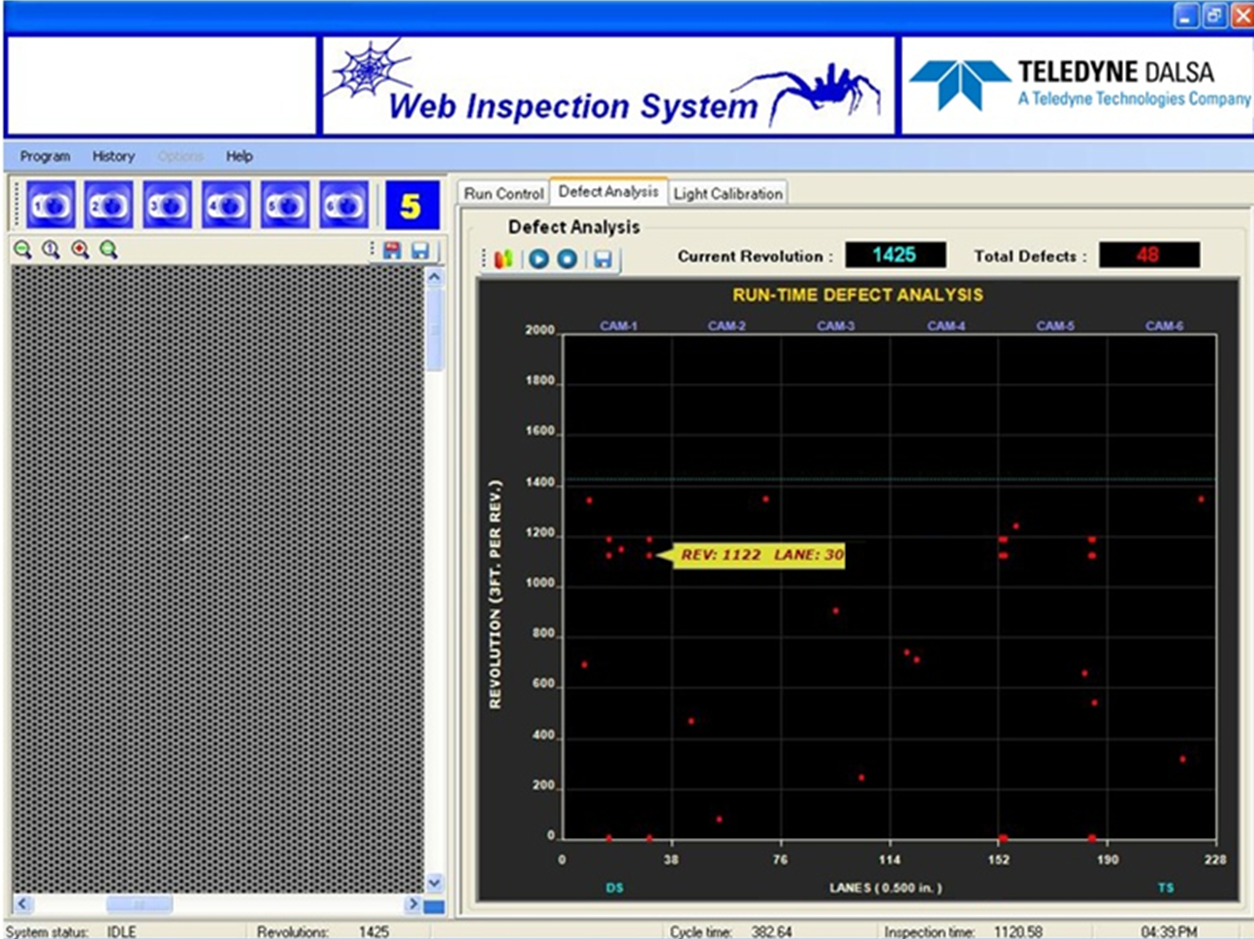
This shows a real-time view (on the left). The roll map, on the right, the y axis identifies linear footage (in roller revolutions) and the x axis shows the defect position. When the product roll is sent for finishing, defects can be picked out as the product is unwound.
Color Line Scan
A color line scan camera isused for inspecting medical trays that incorporate rivets, grommets, and brackets of various colors. These elements could not be easily distinguished and inspected using gray-scale (intensity) images.
A 2K color line scan views 20 inches horizontally across the medical tray; with line scan technology, there is no limit on the vertical size. Two 24 inch line lights illuminate the entire tray, which is moved along a conveyor. An encoder on the conveyor is synchronized so that the color line scan camera triggers as the tray comes into the field of view.
Summary
Line scan cameras are used in vision applications that image large objects, are high-resolution, are high-speed, or need perfect images. Applications where line scan cameras are the best choice include inspecting web materials, as in plastic or paper manufacturing, inspecting continuous “objects” such as road and rail inspection, or where high-quality images are required as in LCD flat panel or in printing inspection.
Teledyne DALSA
Teledyne DALSA is a part of Teledyne’s Vision Solutions group and a leader in the design, manufacture, and deployment of digital imaging components for machine vision.
Discover how Teledyne DALSA can support your automation journey with their complete range of solutions and expertise.
Visit Company Website
Teledyne DALSA is a part of Teledyne’s Vision Solutions group and a leader in the design, manufacture, and deployment of digital imaging components for machine vision.
Global Supply Chain Disruptions Loom Large Over Automation Market
As semiconductor chip shortages persist, advanced automation technology companies must look long term.

How AI Will Revolutionize, Not Replace, Machine Vision
In just 10 years, artificial intelligence (AI) has evolved from a laboratory curiosity to an increasingly pervasive part of life.