Industry Insights
Vision Software, Hardware Adjust to Harsh Environments
Everything is relative.
Ask a webcam perched on a desk what “harsh environments” are, and, assuming it could talk, industrial plants would probably be on that list. They’re dirty, nasty, loud, have random power spikes that would send a webcam to the junk heap, and caring technicians that figure there’s a replacement part somewhere so why bother being gentle. And the webcam wouldn’t be wrong. But it gets worse.
Machine vision systems keep track of robotic drilling machines on oil rigs. They help guide rovers on distant moons and planets. They save soldiers from hidden mines. The harsher the environment, the more likely a machine vision system will be tasked with being the eyes for a human operator safely sitting in a distant control center. With these operational parameters in mind, specialty machine vision suppliers have learned to pay close attention to every aspect of the machine vision design, from the software that runs it all to the cable that connects peripheral to CPU. No detail is too small, either, whether it’s the jacketing material selection, the minutiae of conductor diameter, or unique approaches to 3D vision algorithms that allow machine vision to go where no sane man (or woman) would want to go. When it comes to fielding imaging systems in remote, harsh, and sometimes caustic locations, the details matter when one faulty connection can put a million-dollar machine out of commission.
Big Picture, Big Rigs
David Askey, Chief Business Development Officer for Energid Technologies (Cambridge, Massachusetts), is no stranger to developing image-processing software for some harsh environments. Whether it’s a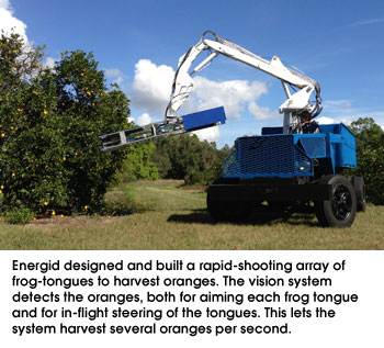 tele-robotic control system for a satellite or high-fidelity vision system simulation for planetary rovers that has to accommodate dynamic range swings that would blind a human eye, Energid doesn’t blink when customers bring tough imaging applications to its doorstep.
“While we’ve developed turnkey systems for the U.S. military and harsh environment simulation for NASA, similar technology applies for autonomous oil rigs in the North Sea,” Askey says. “On the oil rigs, where our Actin software controls 18 robotic systems in open-air environments, the vision technology can make sure that debris, cables, and other systems don’t block the motion paths of the robots, and that connections are up and running and systems are performing as expected. Doing all this while salt spray is flying around in inclement weather makes it an even greater challenge.”
In addition to specific ruggedized hardware solutions for imaging systems in harsh environments, Energid released its Selectin 3D imaging-processing toolkit in 2007 and continues to develop the software today. Selectin, which can run on Windows, Linux, and embedded platforms, came of work done for the U.S. Missile Defense Agency. The software, originally designed to help guide missiles to their targets using real-time imagery, more recently guided a frog-tongue-like harvester to automate the picking of oranges in outdoor light conditions.
Today, Selectin uses target tracking methods to create 3D guidance for robotic automation and industrial applications – specifically applications in noisy environments where particulates, moisture, bad weather, EMI, and physical shocks challenge many 3D image-processing programs.
“Selectin is a model-based 3D vision toolkit, which means we start with a CAD model or other parameters that define our target,” Askey explains. “If we can also get some sense of the lighting environment and how it interacts with the material properties of the target, even better. This allows us to rule out conditions that often confuse 3D image-processing software, such as strong shadows, bright sunlight, and specular surfaces.”
Selectin isn’t made for the casual machine vision user. According to Askey, it’s an image-processing engine that needs to be wrapped into a larger image-processing application environment. By optimizing across both CPU and GPU chip capabilities, Selectin uses blob analysis and other spatial and temporal methods to detect multiple objects in a field of view, and then filters out objects that do not meet with physical criteria set in the original model.
“It can be used with single or multiple cameras, with fixed cameras where the objects are moving, or when both camera and object are moving,” Askey continues. “We use a multiple hypothesis tracker to evaluate all objects in parallel and discard objects that do not meet the model classifiers.”
Small Details Count…A Lot
Tracking each speck of salt as it flies across a camera’s field of view isn’t the only small detail that matters to machine vision in harsh environments.
“We get calls every week from customers that used off-the-shelf cables for a robot guidance application that crashed after a few months because of a faulty cable,” says Treacy Sommer, Vice President of specialty cable manufacturer OCP Group Inc. (San Diego, California).
OCP Group primarily sells specialty cables to OEMs and companies with very special needs. “We go beyond the standard Camera Link or GigE Vision cable to looking at specific materials for jacketing, conductors, and other components that will meet a customer’s unique needs, like resistance to oil and hazardous chemicals, for example, or million-cycle flex cables for robotic applications,” Sommer says.
According to Sommer, many companies offer “flex” cables for robotic applications, but OCP Group looks at the specifics of how the cable will be used and for how long, as well as environmental factors. “When we design a cable, it’s not just how the cable will move in the X, Y, and Z axes, but what torque will be applied to each axis,” Sommer notes. “A welding machine on a car line, for example, goes all over the place. You have to consider torque as well as bend. We have cables that will operate from -40 C to 105 C, moving the whole time; they’re oil, chemical, and UV resistant. We use special jacketing materials and EMI protection sheaths made of finer weaves that can handle high-flex applications. A USB3 Vision cable might use 20 strands of wire instead of seven strands per conductor to handle all the flex and reduce the brittleness of the wire. It all adds to the robustness of the cable.”
With the recent addition of the USB3 Vision standard, cable manufacturers are seeing a lot of interest in compatible cables. “USB connectors are meant to be inserted 500 to 1000 times, but the cable strain relief and the way the conductors are soldered to the connector all have to be taken into account for an industrial cable that will move a lot,” says Sommer. “When you start monkeying around with these components under the hood, so to speak, it can really add to the cost. Casual customers may balk, but experienced integrators understand that you get what you pay for.”
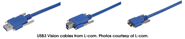
Recently, new AIA member L-com (North Andover, Massachusetts) launched a new USB3 Vision cable line with special screw-down connectors. “L-com’s new line of USB 3.0 cable assemblies is expected to serve two purposes,” explains Steve Smith, Product Manager at L-com Inc. “First, they support the machine vision camera market and are designed per the USB3 Vision specification. Second, they are expected to appeal to several other markets, especially industrial and medical applications where standard USB 3.0 cables fall short with respect to reliability. USB cables rely on friction fit mating that can come loose under vibration by jostling, etc. The 3.0 Vision cables solve this issue by adding thumbscrews, which provide lockdown mating.”
While all machine vision applications require attention to detail to guarantee a successful deployment, harsh environments require special attention to every hard and soft component in the system. While these solutions often demand additional engineering and cost, falling back on webcams and consumer components for the toughest applications means that what works on the bench won’t work for very long in the field. So when it comes to the roughest environments, choose your integrators wisely because in the end, downtime costs much more than quality components.
Ask a webcam perched on a desk what “harsh environments” are, and, assuming it could talk, industrial plants would probably be on that list. They’re dirty, nasty, loud, have random power spikes that would send a webcam to the junk heap, and caring technicians that figure there’s a replacement part somewhere so why bother being gentle. And the webcam wouldn’t be wrong. But it gets worse.
Machine vision systems keep track of robotic drilling machines on oil rigs. They help guide rovers on distant moons and planets. They save soldiers from hidden mines. The harsher the environment, the more likely a machine vision system will be tasked with being the eyes for a human operator safely sitting in a distant control center. With these operational parameters in mind, specialty machine vision suppliers have learned to pay close attention to every aspect of the machine vision design, from the software that runs it all to the cable that connects peripheral to CPU. No detail is too small, either, whether it’s the jacketing material selection, the minutiae of conductor diameter, or unique approaches to 3D vision algorithms that allow machine vision to go where no sane man (or woman) would want to go. When it comes to fielding imaging systems in remote, harsh, and sometimes caustic locations, the details matter when one faulty connection can put a million-dollar machine out of commission.
Big Picture, Big Rigs
David Askey, Chief Business Development Officer for Energid Technologies (Cambridge, Massachusetts), is no stranger to developing image-processing software for some harsh environments. Whether it’s a
tele-robotic control system for a satellite or high-fidelity vision system simulation for planetary rovers that has to accommodate dynamic range swings that would blind a human eye, Energid doesn’t blink when customers bring tough imaging applications to its doorstep. “While we’ve developed turnkey systems for the U.S. military and harsh environment simulation for NASA, similar technology applies for autonomous oil rigs in the North Sea,” Askey says. “On the oil rigs, where our Actin software controls 18 robotic systems in open-air environments, the vision technology can make sure that debris, cables, and other systems don’t block the motion paths of the robots, and that connections are up and running and systems are performing as expected. Doing all this while salt spray is flying around in inclement weather makes it an even greater challenge.”
In addition to specific ruggedized hardware solutions for imaging systems in harsh environments, Energid released its Selectin 3D imaging-processing toolkit in 2007 and continues to develop the software today. Selectin, which can run on Windows, Linux, and embedded platforms, came of work done for the U.S. Missile Defense Agency. The software, originally designed to help guide missiles to their targets using real-time imagery, more recently guided a frog-tongue-like harvester to automate the picking of oranges in outdoor light conditions.
Today, Selectin uses target tracking methods to create 3D guidance for robotic automation and industrial applications – specifically applications in noisy environments where particulates, moisture, bad weather, EMI, and physical shocks challenge many 3D image-processing programs.
“Selectin is a model-based 3D vision toolkit, which means we start with a CAD model or other parameters that define our target,” Askey explains. “If we can also get some sense of the lighting environment and how it interacts with the material properties of the target, even better. This allows us to rule out conditions that often confuse 3D image-processing software, such as strong shadows, bright sunlight, and specular surfaces.”
Selectin isn’t made for the casual machine vision user. According to Askey, it’s an image-processing engine that needs to be wrapped into a larger image-processing application environment. By optimizing across both CPU and GPU chip capabilities, Selectin uses blob analysis and other spatial and temporal methods to detect multiple objects in a field of view, and then filters out objects that do not meet with physical criteria set in the original model.
“It can be used with single or multiple cameras, with fixed cameras where the objects are moving, or when both camera and object are moving,” Askey continues. “We use a multiple hypothesis tracker to evaluate all objects in parallel and discard objects that do not meet the model classifiers.”
Small Details Count…A Lot
Tracking each speck of salt as it flies across a camera’s field of view isn’t the only small detail that matters to machine vision in harsh environments.
“We get calls every week from customers that used off-the-shelf cables for a robot guidance application that crashed after a few months because of a faulty cable,” says Treacy Sommer, Vice President of specialty cable manufacturer OCP Group Inc. (San Diego, California).
OCP Group primarily sells specialty cables to OEMs and companies with very special needs. “We go beyond the standard Camera Link or GigE Vision cable to looking at specific materials for jacketing, conductors, and other components that will meet a customer’s unique needs, like resistance to oil and hazardous chemicals, for example, or million-cycle flex cables for robotic applications,” Sommer says.
According to Sommer, many companies offer “flex” cables for robotic applications, but OCP Group looks at the specifics of how the cable will be used and for how long, as well as environmental factors. “When we design a cable, it’s not just how the cable will move in the X, Y, and Z axes, but what torque will be applied to each axis,” Sommer notes. “A welding machine on a car line, for example, goes all over the place. You have to consider torque as well as bend. We have cables that will operate from -40 C to 105 C, moving the whole time; they’re oil, chemical, and UV resistant. We use special jacketing materials and EMI protection sheaths made of finer weaves that can handle high-flex applications. A USB3 Vision cable might use 20 strands of wire instead of seven strands per conductor to handle all the flex and reduce the brittleness of the wire. It all adds to the robustness of the cable.”
With the recent addition of the USB3 Vision standard, cable manufacturers are seeing a lot of interest in compatible cables. “USB connectors are meant to be inserted 500 to 1000 times, but the cable strain relief and the way the conductors are soldered to the connector all have to be taken into account for an industrial cable that will move a lot,” says Sommer. “When you start monkeying around with these components under the hood, so to speak, it can really add to the cost. Casual customers may balk, but experienced integrators understand that you get what you pay for.”
Recently, new AIA member L-com (North Andover, Massachusetts) launched a new USB3 Vision cable line with special screw-down connectors. “L-com’s new line of USB 3.0 cable assemblies is expected to serve two purposes,” explains Steve Smith, Product Manager at L-com Inc. “First, they support the machine vision camera market and are designed per the USB3 Vision specification. Second, they are expected to appeal to several other markets, especially industrial and medical applications where standard USB 3.0 cables fall short with respect to reliability. USB cables rely on friction fit mating that can come loose under vibration by jostling, etc. The 3.0 Vision cables solve this issue by adding thumbscrews, which provide lockdown mating.”
While all machine vision applications require attention to detail to guarantee a successful deployment, harsh environments require special attention to every hard and soft component in the system. While these solutions often demand additional engineering and cost, falling back on webcams and consumer components for the toughest applications means that what works on the bench won’t work for very long in the field. So when it comes to the roughest environments, choose your integrators wisely because in the end, downtime costs much more than quality components.
MEET THE AUTHOR
AIA
AIA - Advancing Vision + Imaging has transformed into the Association for Advancing Automation, the leading global automation trade association of the vision + imaging, robotics, motion control, and industrial AI industries.
Discover how AIA can support your automation journey with their complete range of solutions and expertise.
Visit Company Website
« Back To Vision & Imaging Industry Insights

AIA - Advancing Vision + Imaging has transformed into the Association for Advancing Automation, the leading global automation trade association of the vision + imaging, robotics, motion control, and industrial AI industries.
Embedded Vision
This content is part of the Embedded Vision curated collection. To learn more about Embedded Vision, click here.
Vision in Life Sciences
This content is part of the Vision in Life Sciences curated collection. To learn more about Vision in Life Sciences, click here.