Industry Insights
From Reflection to Emission, Metal Forming Challenges Machine Vision
 It’s not easy to tame the forces that helped create the universe.
Metal forming uses heat and pressure to create the building blocks of our society. But like the concept of geographic time, it’s hard to grasp just how much heat and temperature it takes to extract metal ores from mined rock, purify that ore into liquid metal, pour it into molds that mirror conditions found in the center of the Earth, and then force that metal into sheets, bars, and other shapes to support our modern society.
Now, imagine you have to supervise that metal production, from the explosive environment of extraction and forging to the rock-crushing forces of cold-forming lines.
It’s hot. It’s uncomfortable. And you could use some help. Luckily, machine vision technology can help keep the hot-forming process safe and cold-forming machines in line with customer specifications.
Never Too Hot
Metal forming starts by extracting the metals from the waste rock using a variety of methods. The metal is then separated and heated until it reaches a liquid phase, then poured into a variety of molds for shipping and later cold forming.
The process is energy intensive, expensive, and dangerous. Industrial vision cameras are regularly used to watch the furnace to monitor the separation process, to monitor the health of crucibles that carry the molten metals, and to monitor the flow of molten metal into molds and other hot-forming systems.
“The heat from forged metal is intense, so there’s always a huge amount of infrared [IR] radiation coming out of it,” explains Steven Kinney, Director Technical Pre-Sales and Support at JAI (San Jose, California). “So almost always in forging applications, you use a strong bandpass filter to block the IR and near-IR [NIR] so that radiation doesn’t oversaturate the camera and degrade spatial resolution because IR radiation is long-wavelength radiation that muddles up spatial information. Because of the amount of IR radiation, you’ll sometimes have to use materials that can absorb considerable heat and electromagnetic radiation and/or water cool the filters along with the camera enclosure.”
Because intense heat emits strongly at the “red” end of the visible spectrum, Simon Stanley, Managing Director of ProPhotonix Ireland (County Cork, Ireland), often recommends to customers that they use blue light sources to balance the available light for imaging.
“And because you can’t have the light or camera right there near the red-hot steel, your camera and lights are often placed at some distance from the object, which means your output needs to be stronger, brighter, and better collimated,” he says.
Stanley adds that ProPhotonix’s background in optics as an evolution of optical powerhouse StockerYale, as well as their ability to work with chip-on-board technology to create their own LED modules rather than buy packaged LEDs from others, helps ProPhotonix maintain precise spectral control of and boost the intensity of their LED lights.
To handle extreme temperatures, ProPhotonix also recommends water cooling. However, cooling will not mitigate all the environmental issues. “Even with cooling, the camera can get pretty hot,” explains JAI’s Kinney. “These cameras need to work in extended temperature ranges up to 70C, not just 40C or 50C. Once upon a time, you could choose sensors that were MILSPEC and designed for extended temperature range operation. But now with FPGAs and ASICs, the camera is a high-end mixed-signal device. And there isn’t even a MILSPEC CCD sensor anymore. Camera manufacturers like JAI have to pay close attention to their electronic designs, test them at high temperatures, and redesign as necessary to avoid hot spots that will limit the camera’s useable life before MTBF acceptable values.”
A side effect of cooling is the possibility of condensation forming during warm-up and shut down. In answer, JAI uses conformal coatings made of thin layers of polyurethane materials originally designed to reduce tin whiskering in low-lead solders. These coatings keep humidity from fouling the electronics.
Finally, Kinney advises to not forget about the cable and communications. As molten metal runs down channels, it creates large magnetic fields very similar to those around solar flares. New networks such as 10 GigE that natively use optical fiber instead of copper are intrinsically hardened to EMI interference. When the application calls for Camera Link, USB, or other networks, fiber extenders are often a good idea to mitigate noise from fouling data streams.
Cold-Forming Sheets and Metal Parts
While forges and hot-forming operations can confound optics due to optical emissions skewed toward the red/IR, cold-forming applications can also benefit from high-dynamic-range (HDR) camera functions and special lighting considerations to accommodate line scan cameras used in metal rolling and other cold-forming applications.
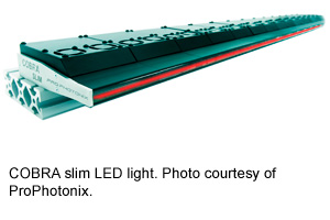
ProPhotonix, for example, can build lights up to 10 m in length using their modular Cobra Slim light for virtually any width line scan machine vision inspection application. Cobra Slim is compact, allowing it to be placed close the metal sheet or other molded metal, which helps for space-constrained applications and maximum light intensity. And by carefully selecting the chip mix in the light, Cobra Slim promises steady spectral output for camera filtering and improved contrast; strong, steady illumination and optics are integrated at the factor to guarantee the lights will meet the OEM or machine builder’s optical performance needs.
After the sheets have been formed, it’s also common to check the stamped features of a metal sheet before being folded into a final shape. This is most commonly accomplished with backlighting to avoid the high-reflectivity challenges from metal surfaces and create good contrast between holes and the metal surface. Due to the high contrast between dark metal surfaces and backlit holes and edges, the camera’s dynamic range is often pushed to the limit.
In these cases, JAI recommends using their HDR software included in their SDK. The HDR module combines pixel values from two consecutive images with different gain settings, extending an 8- or 10-bit image to 12 or 14 bits, depending on the customer’s needs.
“Sheet metal and stamping customers are usually concerned with mils, not microns,” says Kinney. “So even if we get some movement between exposures, the spatial requirements for these types of applications can handle some blurring. The customers typically want a high-contrast image from end to end to look for surface defects, and want to avoid lens and geometric distortion for hole measurements, for example.”
While industrial machine vision components are much more rugged than their consumer counterparts, metal-forging applications can push industrial equipment to the limit. Luckily, companies that regularly work in military and related applications are used to overcoming difficult conditions. Think about that when selecting your next hardware for a hot- or cold-running metal-inspection application.
AIA
AIA - Advancing Vision + Imaging has transformed into the Association for Advancing Automation, the leading global automation trade association of the vision + imaging, robotics, motion control, and industrial AI industries.
Discover how AIA can support your automation journey with their complete range of solutions and expertise.
Visit Company Website
AIA - Advancing Vision + Imaging has transformed into the Association for Advancing Automation, the leading global automation trade association of the vision + imaging, robotics, motion control, and industrial AI industries.