Tech papers
How do Piezoelectric Flexure Nanopositioners Work?
How do Piezoelectric Flexure Nanopositioners Work?
Piezoelectric flexure-guided nanopositioners, precision motion systems for nanopositioning and scanning provide a higher level of performance than tranditional mechanical guiding systems, such as slides, crosse-rollers or ball bearing stages. This is due to the frictionless nature of the flexure guidance system which is does not limit resolution, reproducibility, straightness, and flatness. While flexures provide a relatively short motion range, piezoelectric flexure nanopositioning stages excel when it comes to accuracy, repeatability and geometric performance.
.jpg)
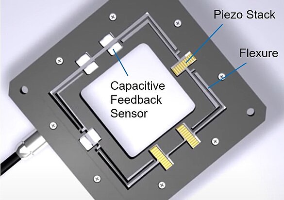
A miniature flexure guided nanopositioner stage
Ultra-Fast Response to Control Inputs
Piezoelectric mechanisms are known for their high acceleration capabilities, which can reach up to 10,000g, which when designed for minimal moving mass, provides an edge for high-speed scanning and dispensing applications. Compared to traditional motorized stages, piezoelectric nanopositioning stages can provide significantly higher scanning speeds, as they can respond to input signals in microseconds.
Piezoelectric flexure mechanisms work by employing a ceramic transducer based on the piezoelectric effect. This effect describes the ability of certain materials to generate an electric charge in response to mechanical stress. When a charge is applied to a piezoelectric material, it deforms and can generate a force that in turn can be utilized to generate motion in a positioning stage or actuator. The position resolution is only limited by the electrical stability of the driving circuit and with modern electronics, sub-nanometer resolution is feasible. When operated with a closed loop controller, nanometer repeatability is achievable.
Piezoelectric flexure nanopositioners also excel with low power consumption, lack of electromagnetic interference
Video: Principle of Piezo Actuators, Piezo Flexure Guided Motion and Piezo Motors
Flexure Guides vs Mechanical Bearings?
Flexure guided motion relies on the elastic deformation or flexing of a solid material, which eliminates friction and stiction while providing high stiffness, load capacity, and resistance to shock and vibration. When designed well, they provide extremely high geometric performance, i.e. guiding accuracy as measured in terms of flatness, straightness, pitch, yaw and roll. Flexures are also wear-free, maintenance-free, lubricant-free and clean-room and vacuum compatible and are not prone to wear and tear.
Video: A fast nanofocusing device with piezo actuators, flexure guides and capacitance feedback
Long Life Piezoelectric Transducers

Ceramic encapsulated PICMA piezo actuators, were installed on the Mars Rover after passing 100 Billion cycles of life testing without failures
At the heart of a PI piezoelectric nanopositioning stage is a multilayer piezoelectric transducer, the Mars-Rover tested PICMA piezo stack. Featuring a cofired ceramic encapsulation in place of conventional conformal coating, it is completely outgassing free and much better protected from environmental influences compared to traditional piezo stack transducers.
Nanopositioner Stage Metrology – How to Measure Nanometer Sized Steps
In order to attain nanometer and sub-nanometer motion with high repeatability, an internal high precision position sensor and closed-loop controller are essential.
The internal metrology system of the stage must also possess the capability to measure motion at the nanometer scale. When selecting a stage metrology system, five primary characteristics must be considered: linearity, sensitivity (resolution), stability, bandwidth, and cost. Other factors include the ability to measure the moving stage platform directly and whether the measurement is contact or noncontact. In piezoelectric nanopositioning applications, three types of feedback are often used: capacitance, strain gauge sensors (film and piezo resistive, and LVDT)
Capacitance Gauges
Many of PI's nanopositioners use capacitance feedback sensors that measure the distance between two plates based on electrical capacitance. They can be seamlessly integrated into nanopositioning stages with minimal impact on the size and mass (inertia). Capacitance feedback sensors deliver the best compromise of position resolution, stability, and bandwidth. They facilitate direct measurement of the moving platform without contact.
When used with PI's digital motion controllers, digital polynomial linearization of mechanics and electronics, overall system linearity errors can be as low as 0.01% making capacitance feedback sensors are the preferred metrology system for the most demanding applications.
.jpg)
Response of a PI piezo nanopositioning stage to a square wave control signal shows true sub-nm positional stability, incremental motion and bidirectional repeatability. Measured with external capacitance gauge, 20pm resolution.
Get the Training You Need for a Safer Workplace!
Autonomous mobile robots are one of the fastest-growing segments of the robotics industry. During this live virtual training, you'll be introduced to safety protocols and best practices for working with mobile robots in industrial settings.
Learn more and register now for upcoming training dates.
Video: Principle of capacitance gauge equipped nanopositioning stages in AFM / SNOM microscopy applications
Strain Gauge Sensor
There are two types of strain gauge sensors: Resistive film sensors and piezoresistive sensors. Piezoresistive strain sensors provide higher sensitivity, film sensors provide higher linearity. Both types are bonded to the piezoelectric transducer or on a flexing element of the nanopositioning stage. They provide high resolution and bandwidth, require very small integration space and are often preferred for cost-sensitive applications. Being contact type sensors, they indirectly measure the position inferring it from strain somewhere in the drivetrain, a flexure or piezo transducer itself.
Full-bridge implementations with multiple strain gauges per axis provide the best temperature stability. Due to the lack of a conformal coating, PI's PICMA cofired piezo transducers allow a closer contact between the strain sensor and the piezo element thus delivering better stability and faster response.
LVDT Transducers
In an LVDT (linear variable differential transducer) a magnetic core, affixed to the moving part of the actuator or nanopositioner, produces a change in inductance proportional to the position change. LVDT sensors enable noncontact, direct position measurement. They are cost-effective, highly stable, and repeatable.
Parallel and Serial Kinematics Multi-Axis Mechanisms
There are two methods for achieving multi-axis motion: parallel and serial kinematics. Serial kinematics motion and positioning systems (nested or stacked systems) are simpler and less expensive to implement, but they have certain limitations when compared to parallel kinematics motion and positioning systems.
In a multi-axis (multi-degree-of-freedom) serial kinematics motion and positioning system, each actuator (and typically each sensor) is assigned to only one degree of freedom. In contrast, in a parallel kinematics multi-axis motion and positioning system, all actuators directly act on the same moving platform (relative to a fixed reference). This allows for a reduction in size and inertia and eliminates micro-friction caused by moving cables. As a result, identical resonant frequency and dynamic behavior can be achieved for both axes. The benefits include higher dynamics and scanning rates, improved trajectory guidance, and greater reproducibility and stability.
Principle of a 3-DOF PI XYΘz, nanopositioner. Minimum inertial-mass is made possible by the monolithic, parallel kinematics design. Accuracy, responsiveness, straightness and flatness are superior to stacked (serial kinematics) multi-axis motion and positioning systems.
Direct Parallel Metrology - Multi-Axis Motion Measurements Relative to a Fixed Reference
Implementing Direct Parallel Metrology is facilitated by parallel kinematics. Although this is a more challenging design in nanopositioners , the performance advantages are evident. In contrast to serial kinematics, where each actuator is assigned to a specific degree of freedom, parallel kinematics enables all actuators to act directly on the same moving platform, relative to a fixed outside reference, resulting in reduced size and inertia, and eliminating micro-friction caused by moving cables.
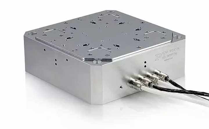
A piezo-flexure guided, 6-axis, closed-loop, sample positioning stage based on a parallel-kinematic design and capacitance gauges for position feedback. The stage was designed for AFM / semiconductor applications. The XYZ resolution is better than 0.1 nm. Three more rotary axes are used for error compensation, to achieve the highest geometric performance.
The use of a parallel metrology sensor array enables measurement of all controlled degrees of freedom relative to a fixed reference. This provides superior multi-axis precision, repeatability, and flatness as all motion is inside the servo-loop, regardless of which actuator caused it. Direct parallel metrology also allows for stiffer servo settings, leading to faster response times. Any off-axis disturbances, whether internal or external, such as induced vibration caused by a fast step of one axis, can be damped by the servo.
.jpg)
Nanometer scale flatness of an parallel-metrology, active-trajectory controlled nanopositioning stage over 100x100µm scanning range of a compact nanopositioner.
More information on Nanopositining Stages
Motion Contollers for Nanopositioners?
Motion controlles and control algorithms play an important part in the overall performance of a nanopositioner system.
An overview of the latest generation of motion controllers is available here.
PI (Physik Instrumente) LP
PI is a leading manufacturer of precision motion control and automation systems, hexapod 6-axis parallel robotic stages, air bearing motion systems, Gantry Systems, 3D printing, laser machining, and piezoelectric nano-positioning solutions. Applications include photonics, semiconductor technology, medical engineering, assembly, inspection,
Discover how PI (Physik Instrumente) LP can support your automation journey with their complete range of solutions and expertise.
Visit Company Website


PI is a leading manufacturer of precision motion control and automation systems, hexapod 6-axis parallel robotic stages, air bearing motion systems, Gantry Systems, 3D printing, laser machining, and piezoelectric nano-positioning solutions. Applications include photonics, semiconductor technology, medical engineering, assembly, inspection,
Piezoelectric Transducers for Liquid Handling, IVD, PoC, Cytometry, Array Spotting
This webinar explains the performance of piezoelectric transducers for Invitro Diagnostics and other medical applications.
Ultrasound Transducers for Therapeutic and Surgical Instruments
Piezoelectric Ultrasound Transducers are used for Carrying Out Contactless Therapies in Catheter Instruments