Tech Papers
Safety Mats
Presence sensing mats combined with a safety mat controller improve productivity while providing access guarding. Less downtime occurs because it is not necessary to set up or remove mechanical safety barriers during operation and maintenance.
Presence sensing mats and controls are used where perimeter access guarding is required, such as around robots, manufacturing work cells, food processing equipment and automated assembly equipment.
Mats and controllers should be designed to meet the applicable sections of ANSI B11.19-1990, OSHA 1910.212 and EN 1760-1:1997.
Theory of Operation
Multiple safety mats may be wired in series to form a complete floor-level guarding system. Each 4-wire safety mat operates on a low-power DC signal. A signal is transmitted through the upper and lower plates separately via the two wires connected to each plate. The signals through the safety mats are monitored by the mat controller.
When the safety mat is not exposed to sufficient actuating force, the signals are unimpaired. The output relays in the controller are energized permitting the guarded machine to run.
When sufficient pressure is applied to the active mat area, the conductive plates touch causing the output relays in the controller to de-energize and a stop signal is issued to the machine.
If a wire should break, separate from a plate, or become disconnected from the controller, the output relays in the controller will de-energize and a stop signal will be sent. Should the safety mat be punctured and the plates short together in a similar manner as being stepped on, the controller will not restart until the punctured mat is replaced.
Safety Distance Calculation
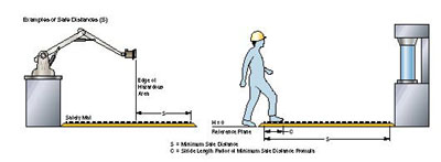
The first and by far the most important consideration is the calculation of the safety distance. There is a minimum mat size that should be placed between a worker and a hazardous motion. Many users will ‘‘eyeball’‘ the application, look at the area where a machine operator would stand and say, ‘‘that looks like it needs a 24-inch wide mat.’‘ It may not be enough.
In standard B11.19 the American National Standards Institute (ANSI) states that, ‘‘The safety mat device shall be located such that the operator cannot reach the recognized hazard before hazardous motion of the machine has ceased.’‘
Unfortunately, the ANSI standard stops there. In order to figure out how much mat you need between a machine and a worker, it’s necessary to refer to the standard EN 999. This standard provides a formula for determining the correct mat size for a specific hazard. The formula is similar in nature to another calculation, which some readers may be familiar – the mounting distance formula for a safety light curtain.
The mat formula reads as follows:
S = (63 in./sec. x T) +
(47.2 in. – 0.4H)
where:
S = The minimum distance from the danger zone to the detection zone in inches. This calculation assumes that the approach of a person toward a dangerous area is at walking speeds.
T = t1 + t2
T = The overall system stopping time.
t1 = The maximum time between the actuation of the safety mat and the controller output relays being in the de-energized state.
t2 = The response time of the machine being guarded. The time required to stop the machine or remove the risk after receiving the output signal from the mat system.
H = The distance above the reference plane (floor) in inches. When mats are mounted on the floor, H = 0.
Example:
As an example, let’s say the stopping time of the guarded machine is 0.300 seconds. The response time of the mat system is 0.025 seconds. The safety mat is to be mounted at the reference plane (floor).
S = (63 in./sec. x T) +
(47.2 in. – 0.4H)
or
S = (63 in./sec. x (t1 + t2)) + (47.2 in. – 0.4H)
Therefore:
S = (63 in./sec. x (0.300 sec. + 0.025 sec.)) + (47.2 in. – (0.4H x 0.0in.))
S = (63 in./sec. x 0.325 sec.) + (47.2 in. – 0.0 in.)
S = 20.5 in. + 47.2 in.
S = 67.7 in. or 1720 mm
This calculation specifies that the distance starting at the mat edge furthest from the hazardous location should be at least 67.7 inches. This also implies that the floor area, from a distance of 67.7 inches to the hazardous location must be guarded by mats or other means, such as fencing, to prevent any undetected access to the hazardous location. Using this formula will usually result in a larger safety mat specification than most people would estimate.
Minimum Detection Zone
The distance a person walks is generally a factor of the walking speed and the stride length. As we have already seen, the positioning of safety equipment, determined by these calculations assumes a person is walking. The stride length affects the minimum size of the mat detection zone. The EN 999 standard has determined that this dimension is equal to 750 mm or 29.5 inches. Thus, the minimum size of a safety mat, measured toward the direction of movement should be at least 29.5 inches, and is identified as ‘‘C’‘ in the figure.
Installation
Surface Preparation
The surface on which the safety mat(s) will be placed should be flat, smooth and free of debris. Any debris left under the mat, in time, may work its way through the housing and eventually contact the electrode assembly. This may affect the mechanical switching of the electrode assembly and will provide a path for moisture to enter the mat. These conditions may lead to a mat failure.
Proper Care of the Safety Mat Cables
After the mat is in place, use care in routing the mat cables to prevent damaging the insulation or breaking the internal wires. Make sure that the cable passageways are free of burrs and sharp edges. Where the mat cable is to enter and exit from under the trim, the trim or mounting surface must be grooved or notched so as not to pinch the cable when the trim is tightened down.
Unless extra precautions are taken to make a watertight connection, never make a cable splice at floor level where the presence of moisture is a possibility. Moisture present at a non-watertight connection will work through the cable and into the mat (i.e. capillary action or wicking).
Safety Mat Mounting Trim
ANSI standard B11.19 also states that, ‘‘Whenever possible, the mat should be fixed in place in such a manner so as to prevent easy relocation or removal by the operator or other unauthorized personnel.’‘
Perimeter trim can help with this requirement, but users need to be aware that not all perimeter trim is the same. Three of the most optimum types of trim include two-part perimeter ramp trim, blunt trim, and two-part joining trim.
Two-part perimeter ramp trim holds mat in place and simplifies installation by providing an aluminum base with channels for running cables, and a snap-on PVC cover. Blunt trim is used where a mat needs to be secured in place, but the edge being secured does not present a trip hazard. Two-part joining trim is used to create an active area between two adjacent mats.
Robotic Industries Association
RIA has transformed into the Association for Advancing Automation, the leading global automation trade association of the robotics, machine vision, motion control, and industrial AI industries.
Discover how Robotic Industries Association can support your automation journey with their complete range of solutions and expertise.
Visit Company WebsiteRobotic Industries Association 
RIA has transformed into the Association for Advancing Automation, the leading global automation trade association of the robotics, machine vision, motion control, and industrial AI industries.