Tech Papers
Part-Speed Position Synchronized Output
Part-Speed Position Synchronized Output (PSO) is a new tracking mode for Aerotech’s PSO advanced controller feature. Part-Speed PSO commands high-speed, low latency output pulses based on the commanded vector velocity.
Extending PSO Capabilities
Aerotech’s PSO controller feature has long been used by industrial and research users alike to command their process tool – a laser, sensor, camera, or other device – at very high repetition rates and with extremely low latencies. The seamless integration of process and motion control is one of the factors that make Aerotech’s controllers highly desirable.
PSO normally requires direct access to up to three axes of encoder feedback in order to calculate the vector distance traveled. Requiring access to real position has its benefits, but has been a limiting factor in the adoption of PSO for some applications. Due to the sum of the squares equation used to calculate the spacing of PSO firing events, traditional X/Y/Z Cartesian systems were required to use PSO.
Part-Speed PSO enables the user to access PSO capabilities even when encoder feedback is nonlinear or not accessible. With Aerotech’s A3200 controller and Part-Speed PSO, control of the PSO output can be based on the velocity command of your process tool with respect to the part being processed. This capability enables PSO to be used in several new situations, such as:
1. The part-space (programming) coordinate space is not identical to the machine-space (motion axes) coordinate space. This can occur for reasons such as:
- The X/Y/Z position command is modified by a kinematic transformation (4-axis systems, 5-axis systems, 3-axis galvo scanners, hexapods, etc.).
- Tool normalcy is achieved via a rotation axis.
- A linear move is achieved by using nonlinear axes. (Figure 1 depicts a system in which motion in the Y direction may be achieved by translating the Y axis and also by rotating the A axis).
2. The type of encoder feedback required for the PSO hardware circuit is not accessible. This can occur because:
- Non-compatible PSO feedback devices are being used (absolute encoders).
- Desired reduction in wiring complexity.
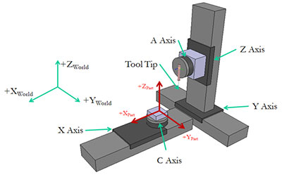
Figure 1. A five-axis machine configuration is shown. In this configuration, the user programs in X/Y/Z “part” space and motion is commanded to the X, Y, Z, A and B “real” axes. The A and B axes are typically used to maintain normalcy between the process tool and the surface of the part being processed.
Programming Part-Speed PSO
The following programming example uses these axis configurations:
- X and Y are virtual axes within the work space.
- x is a real axis (in other words, an actual drive connected to the A3200 controller network).
Also note that x may not be the only real axis being commanded. However, it is the axis that contains the physical PSO output and hardware.
Part-Speed PSO is configured by extending the use of pre-existing A3200 commands:
- The PULSE SET OUTPUT command can now be configured to generate an internal signal that can be configured as an input to PSO.
- The PSOTRACK INPUT command and PSOWINDOW INPUT command can now be configured to use the PULSE output.
The PULSE SET OUTPUT command is used to establish which axes will be used to generate the tracked velocity command, which is calculated using the square root of the sum of squares of the components of each axis specified. In the example program, virtual axes X and Y are tracked. The PULSE SET OUTPUT command is also used to determine which real drive will receive the velocity command. In this example, it is the “real” x axis.
For that reason, the “real” x axis is the axis that receives all of the PSO commands, including the PSOTRACK INPUT command.
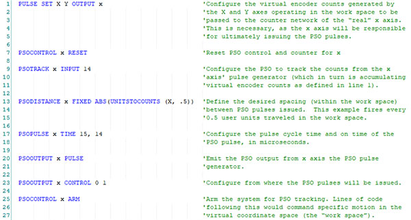
Example Program Setting Up Part-Speed PSO
In another recent Aerotech white paper, Customized Relationships and Coordinated Motion with AXISSTATUSFAST, it was discussed how the A3200 controller allows for advanced kinematic relationships to be quickly implemented. Although not thoroughly discussed in this particular white paper, pairing together a kinematic program (often running on a separate controller programming “task”) with Part-Speed PSO demonstrates the most advanced implementation of this new controller feature. As you program to virtual axes and use the commanded vector velocity of virtual axes as the input to the PSOTRACK INPUT command, the separate kinematic program commands the real axes to effectively move your work point as you have commanded the virtual axes.
Technical Considerations
The following should be considered when implementing Part-Speed PSO.
1. The PULSE command pulse generator output is limited to a 24 MHz output rate. The CountsPerUnit parameter and programmed velocity (feed rate) of the virtual axes will determine the PULSE command pulse generator output rate. The maximum allowable programmed velocity, referred to as “FeedRate”, may be determined from the equation:
FeedRate = EncoderCountFreq/CountsPerUnit
where EncoderCountFreq = 24 MHz.
2. The CountsPerUnit parameter should be chosen such that the resolution of the virtual axes in the work space is smaller than the PSODISTANCE specified within the program configuration (reference line 13 in the example code).
3. The PSO outputs on Aerotech drives have an output frequency limit for PSO output pulses. Refer to Help topic “PSO Specifications” for values of specific drive types. Using the referenced frequency limit, the minimum spacing between pulses can be determined from the equation:
MinSpacing = FeedRate/LaserOutputFreq
where LaserOutputFreq is the value determined from the referenced Help topic.
Aerotech, Inc.
Aerotech designs and manufactures the highest performance motion control and positioning systems for customers in industry, government, science, and research institutions around the world. Aerotech's precision motion control products provide the critical performance for today's demanding applications in markets such
Discover how Aerotech, Inc. can support your automation journey with their complete range of solutions and expertise.
Visit Company Website
Aerotech designs and manufactures the highest performance motion control and positioning systems for customers in industry, government, science, and research institutions around the world. Aerotech's precision motion control products provide the critical performance for today's demanding applications in markets such

Part II: Making the Intelligent Factory Today
What are the tools and techniques you can apply right now to begin reaping the benefits of the industrial IoT?
Allied Motion Secures New $125 Million Credit Facility
Refinancing expected to reduce annual cash interest expense by approximately $3.3 million on a pre-tax basis ($2.2 million after tax)
2012 MCA Business Conference Speaker and Presentation List
2012 MCA Business Conference Speaker and Presentation List