Industry Insights
Using Electronic Adjustable Speed Drives to Replace Other Methods
For years many methods have been used to vary the speed of a driven shaft. From mechanical linkages to pulleys to adjustable speed drives, all methods work, but with pros and cons. This paper will deal with the many variances and show how electronic adjustable speed controls without mechanical problems will provide a more reliable solution.
ASD theory:
The speed of a 3-phase induction motor is based on line frequency. In the U.S., this frequency is 60Hz or 60 cycles per second. Motors are designed with a certain number of motor poles. Probably the most common is a 4-pole motor. Using the equation below, the synchronous speed of the motor can be determined.
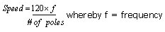
Thus a 4-pole motor running across the line in the U.S. would have a synchrotrons speed of 1800RPM. However all motors do exhibit some slip at full load therefore more than likely the motor rated speed would be near 1750-1780RPM. An adjustable speed drive is useful in changing the actual frequency the motor sees. A typical ASD takes incoming line voltage and converts it to DC voltage. See Figure 1.
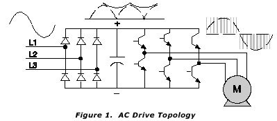
That voltage is then filtered to take out the ac ripple. Then using transistors, the DC voltage is then “inverted” back to AC. Since the transistors are controlled via a processor, any particular voltage and frequency can be regulated to the motor. In this manner any desired speed can be set simply by adjusting the frequency the motor receives. You may hear terms such as Variable Frequency Drive, Inverter, or Adjustable Speed control and all mean the same thing. Taken the Inverter one step further is the Vector drive. Vector drives use encoder feedback to determine actual speed. Then by separating the torque producing current from the flux current, the vector drive can produce full torque down to zero RPM. The overall torque curve of an ASD is shown in Figure 2. A standard open loop control performing a turndown of 10:1 is standard. Adding an encoder and using vector technology, turndown can be over 1000:1. Turn-ups are only limited to the mechanical limitations of the motor since the drive can create frequencies up to 1000Hz. Note from the diagram that the HP remains constant beyond base speed. No belt can provide the same flexibility. Even easier on the setup is that of infinite numbers of speed changes and most of all, no belts or springs to maintain, no friction losses and no more maintenance calls. HP ranges for ASDs have recently made it into the 2000HP+ range for low voltage controls (600V or less).
Mechanical systems:
Variable pitch pulleys are a simple mechanical method to change the speed of the load. Several different manufactures offer many solutions based on the turn-down or turn-up ratio. In its simplest form, one pulley adjusts and the other pulley is spring-loaded. The ratio of the adjustable pulley is then opened or closed to adjust speed and the spring-loaded pulley self-adjusts in the opposite way. More advanced pulley system will be mechanically linked so to that as one pulley is open or closed, the opposing pulley is changed as well, this assures the operation that the belt is not going to slip. See Figure 3a and 3b. As with any mechanical gear change, whether it be a true gearbox or a ratio up or ratio down pulley system two things are inversely proportional, Speed vs. Torque. As the load goes faster, the torque drops and conversely as the load goes slower, the torque goes up. This may be useful in cutting applications where high torque is needed on a drill bit for cutting, but low torque high speeds for polishing/finishing cuts. Typical ratios are normally 3:1, but can be as high as 9:1. HP limitations are usually around 50HP. Guards must be maintained to prevent contact with rotating equipment, thus these can be a safety hazard.
Taking it even one more step, a pneumatic or hydraulic system can be added to do the mechanical change without manual adjustment. With a simple PID controller, this can be automatic.
However, one thing that must be considered anytime this setup is used is the load torque. Anytime the driver is turning faster than the load, the available torque on the load goes up. This can pose a problem when simply trying to change speed, but maintain the same available torque. Another issue is that of wear and tear on the belt and springs. Overtime, the springs will lose their effectiveness and the belt will become looser and begin to slip thus resulting in its loss as well. If the springs are overtightened, then the belt creates more drag and further losses occur. So, much engineering effort must be involved up front for sizing and scheduled future maintenance if this method is used.
ASDs are a perfect fit when torque does not need to change only the speed. Since the drive has no moving parts, there is no mechanical wear and tear to deal with. If the operation requires speed changes at any ratio, the drive can handle it without the need to change pulleys and belts.
Another method of changing speeds other than the variable pulley method is that of the traction drive. In this method two rotors are meshed together at varying angles to adjust speed. See Figure 4a and 4b.
Due to the change in contact point, the load speed is changed. These are best suited for continuous loading applications. Spike loading is not allowed as slippage can easily occur and quickly reduce the length of life of the moving parts. Another type of traction drive is shown below in Figure 5.
Drive balls mounted on these tiltable shafts press upon the faces of the input and output cones. By moving a lead screw, the ball tilts the shafts to increase or decreases the overall speed ratio. These are an efficient method of speed changing, but not effective with shock loads.
An adjustable speed control in this case can tolerate the spike loading and can reduce the transient seen from the “shock”. With continuous current regulation, the control will reduce peak currents to a reasonable level. Even those with the worst shock loading like rock crushers can benefit from this type of control. The downside is of course no increase in torque can be accomplished with an adjustable speed control, but overspeeding is not a problem unless mechanical reasons in the motor prevent it.
Moving away from speed reduction, the subject will change to following using mechanics. Some machinery relies strictly on one motor with multiple gearing to provide synchronous motion throughout the machine. See Figure 4. As parts wear, this gearing will usually become asynchronous, thus resulting in a poor product. The user must repair the machine by replacing the gearing. Making adjustments is not easy, either. Both are costly solutions. And then in the case of a web process, adjusting for slack is difficult as well. An Adjustable speed drive and in this case the Vector version will provide a simpler method. See Figure 6. Instead of using (1) 20Hp motor with mechanical links, (4) 5HP drives/motors are used instead.
Using a line shaft encoder (or the encoder from another control), an unlimited amount of motors can be connected to run ina daisy chain or parallel configuration. Since we are dealing with electronics and no longer with mechanical links, the wear and tear is eliminated. If the machine needs adjustment it is a simple parameter adjustment in the control and not a rebuild of the machine. If slack needs to be corrected, then a simple input change can remove the slack from the web. Incorporating this electronic gearing, the accuracy can be maintained down to +/-1 encoder count and can manipulate any gearbox range. Should the process get changed or different materials used, it is a matter of only adjusting the ratio in the control. No mechanical changes are necessary. That’s a cost savings!
Eddy Current clutches are another method of adjustable speed control. By adding an inductive type clutch onto the motor, the load speed can be varied. Eddy current clutches can provide regulation down to 0.5% of max speed when the load goes from 10% to 100%. (From no load to full load, the regulation is usually 3% or more) In the case of an Eddy Current clutch, the motor is started across the line, with the clutch disabled (no current flow). After the motor has reached its speed, its controller engages the eddy clutch. See Figure 7.
Eddy current clutches are made up of a field, a tachometer, and an eddy current control module. The Control module supplies DC current to the clutch, which in turn causes the load to spin. Feedback from the tachometer is fed to the control module in a PID setup. The more torque that is required by the load, the more current is needed to be supplied to the clutch to prevent slippage. In the case of no load, the least amount of leakage into the clutch and the shaft spins, so no load with zero speed is extremely tough to regulate. In the case of the Eddy Current clutch, no additional torque can be supplied to the load. At best case, the load attached to a clutch would see 95% of the speed of the motor or in the case of a 1780RPM drive motor, the load would spin at 1690RPM. So, the load would never see full speed. This must be taken into account when sizing for speed and torque.
An adjustable speed control changes the frequency to the motor, thus it is speed directly proportional to the Frequency supplied by the motor. The only exception is that the motor does inherently have “slip”. Thus a 4-pole motor might operate at 1780Rpm at full load and 1800RPM at no load when operated at 60Hz. However, in this case, you would get the full range of the motor and unlike the eddy current clutch, with the ASD attached, overspeeding is possible.
Conclusion:
There are many methods in which speed control can take place. Most mechanical methods do work great and are easy to understand. However, maintenance can become a headache in both labor and replacement costs. As machinery is upgraded to perform faster and quicker, mechanical solutions usually require a full replacement. With competing companies, staying on top is a must. In the case of Adjustable Speed controls, changing speeds or torques is usually a matter of parameter changes, which can be done on the fly. They have no mechanical failures and everyday faster processors and more memory are added, thus their “intelligence” grows more. Be sure to weigh the options of mechanical vs. electronic when setting up a machine to have speed control.
Motion Control & Motor Association
The Motion Control and Motor Association (MCMA) – the most trusted resource for motion control information, education, and events – has transformed into the Association for Advancing Automation.
Discover how Motion Control & Motor Association can support your automation journey with their complete range of solutions and expertise.
Visit Company WebsiteMotion Control & Motor Association 
The Motion Control and Motor Association (MCMA) – the most trusted resource for motion control information, education, and events – has transformed into the Association for Advancing Automation.
A Perfect Drive Solution in Only a Few Steps
New, Speed motors and controllers from maxon.
Taiwan Excellence to introduce 15 award-winning Taiwanese advanced technology brands at AUTOMATE 2025
Incorporating the theme of “Advancing Robotics with Taiwanese Precision,” the Taiwan Excellence exhibit in Hall B, Booth 2646, will showcase