Industry Insights
Understanding Motion Control Networks II: Safety
Part two of this two-part article reviews safety protocols for industrial automation. Part one discusses network models and the most popular industrial networking protocols for motion-control applications.
The industrial fieldbus did more than just streamline machine design and operation. It provided an essential support structure for machine-level safety. Prior to networking, the dominant approach to safety involved hard-wired relays that cut power to equipment when conditions were violated - enclosures opened, light-curtains breached, etc. That required point-to-point wiring for each set of conditions, which added to cost and complexity. Recovery involved not just addressing the issue that caused the fault but restarting the equipment, adding to the length and cost of downtime.
With the addition of safety PLCs and safety-enabled drives, automation safety has moved beyond the core mandate of employee health to also support the health of assets and the manufacturing process itself. Relays define a single response to a single condition: When the enclosure is opened, for example, cut power to the motor. Safety drives make it possible to define multiple conditions and multiple responses: When the enclosure is opened and the operator has the password, operate in Safe Speed mode to enable faster cleaning. When torque demand exceeds a certain threshold, boost current but also send a notification to the HMI and to maintenance.
To truly take advantage of the technology, safety devices and controllers need to be linked by a single communications network. Although this can take place over a dedicated safety network, that implementation adds cost and complexity. With the aid of dedicated safety protocols, plant-floor networks can be used to carry safety communications at the same time as automation data and without compromising either objective.
The Open System Interconnection (OSI) Model
Before we dive into the specifics of safety protocols, a quick review of the OSI model. The model divides the process of sending data from one device to another into seven stages, as shown below:
Layer 1: the physical layer, e.g., RS 232, RS 485, IEEE 802.3 (Ethernet), CANbus, IEEE 802.11 (wireless Ethernet), etc.
Layer 2: the data-link layer, which governs node-to-node communications
Layer 3: the network layer, which enables messages to travel from node-to-node across the network (e.g., IP)
Layer 4: the transport layer, which packs up the data to send to the next layer (e.g., transmission control protocol (TCP), user datagram protocol (UDP), etc.)
Layer 5: the session layer, which manages communication sessions to exchange data
Layer 6: the presentation layer, which involves data translation between the network and the application
Layer 7: the application layer, where many industrial Ethernet protocols reside
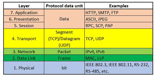 The transmission process begins in layer 7, the application layer. The data gets packed into a frame and wrapped with headers that identify it and describe how it should be passed off to the next layer. The process repeats at each layer with additional headers until by the time the transmission reaches the physical layer, it contains not just I/O but full information about where it originated, where it should go, and how it should be processed and transferred en route.
When the transmission arrives at the destination node, the header information enables it to be unpacked layer by layer and reassembled into the full data set. In this way, a PC can send a job to a printer or a safety PLC can send an alarm to an HMI.
To ensure the deterministic communications required for high-speed automation, many industrial Ethernet protocols deviate from the standard seven-layer model (for more details, read part one). Each of them functions in a slightly different fashion. To enable them to support safety communications, complementary safety protocols have been developed.
 Safety Networks
Functional safety is an active process for ensuring safety. An enclosure that blocks operators from entering a hazardous area would be considered passive safety. A framework that cuts power to the motors when that enclosure is opened is considered functional safety. The IEC 61508 functional safety standard for electrical, electronic, and programmable electronic devices describes a black channel approach to enable industrial fieldbus to support safety communications.
A black channel is basically the communications analog of a black box. From a systems perspective, the inner workings of the black box are irrelevant???what matters are the input and the output. Similarly, designating the existing fieldbus as a black channel means that the physical communications channel is transparent to the rest of the system. Safety functionality rests with the input and output couplers and the safety protocol, which is considered a layer-7 application. Layer 1 through 4 components like switches, routers, and backplanes only need communicate the signal, they don’t need to carry safety-integrity level (SIL) ratings like SIL-3 (probability of less than 10^-8 - 10^-7 dangerous failures per hour during continuous mode of operation).
In a real-world system, we can make two assumptions - components will eventually fail and there will eventually be communications errors in the network. The safety hardware and protocol need to be built so that when a component fails, the system is brought to some known, safe state. Similarly, if there is a communications error, whether that is a lost packet, corrupted data, or a network shut down, the safety software needs to detect that event and take whatever action necessary to bring the equipment to a known, safe state.
If the black channel does not have to be safety qualified, then the software needs to be designed in a way that enables it to identify any errors in the data file and the transmission process. IEC 61784-3, Functional safety fieldbuses - General rules and profile definitions, calls for the communications link to consume no more than 1% of the error budget. Based on the numbers above, that means that communications need to b operate to probability of failure per hour of 10^-9.
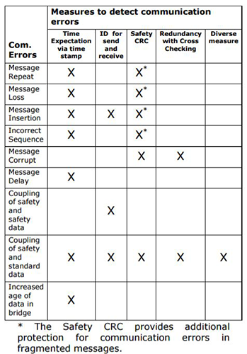
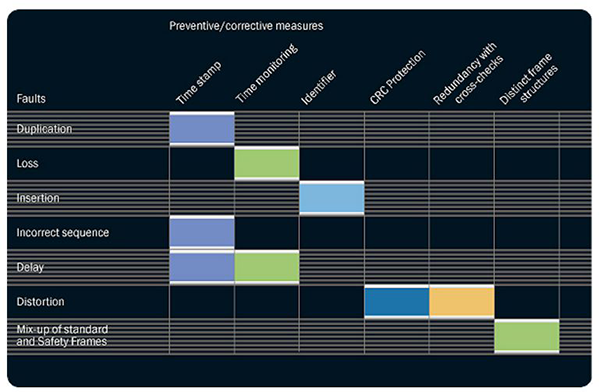
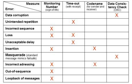
IEC 61784-3 defines transmission error sources and software approaches used to address them. They include:
- Data corruption
- Unintended repetition
- Incorrect sequence
- Data loss
- Unacceptable delay
- Insertion
- Masquerade (non-safety data identified as safety data)
- Incorrect addressing
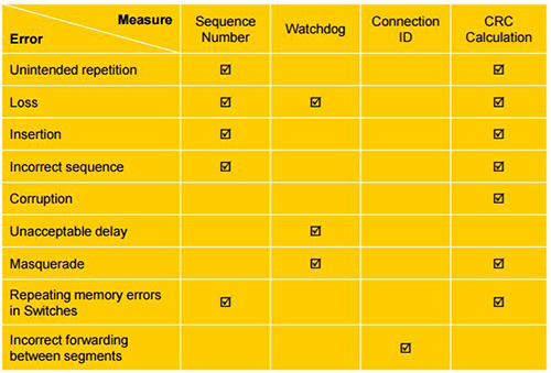
The following software techniques can be used by safety protocols to identify transmission errors:
- Sequence numbers: Detect repetition, incorrect sequence, data loss, data insertion, and standard data masquerading as safety data.
- Timestamps: Detect delays, incorrect sequence, data insertion, and masquerade.
- Identifiers: Detect incorrect addressing and masquerade.
- Data integrity checks via cyclic redundancy check (CRC) or checksum: Detect data corruption, incorrect addressing, and masquerade. The ability to detect data corruption depends upon the nature of the corruption and the implementation.
That last point merits additional discussion. CRC is often discussed as a type of checksum but the two are actually different. Implementations vary widely but in general, checksums look for the remainders left after a mathematical operation on the binary data - typically a division or addition step. If a bit has flipped, the remainder will change, flagging a corrupted data file.
CRC also performs a mathematical operation but based on polynomic math. CRC techniques tend to be better for errors of two bits or better. It’s important to note, however, that a corrupted file may still have the same CRC value as the uncorrupted version. As a result, the choice of CRC technique is essential to accurate results.
Safety Protocols
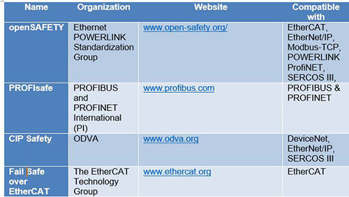
The safety protocols discussed here have multiple things in common. They are all based on the black channel concept. They transmit safety data by embedding it in the standard data frame. This ensures deterministic communications. The addition of error-detection tools as discussed above helps ensure that the safety messaging gets where it needs to go, when it needs to arrive.
Certified Motion Control Professional Program
Strengthen Your Skills and Enhance Your Career

Become a Certified Motion Control Professional (CMCP) and join the elite group of system integrators, machine builders, manufacturers, end-users and others recognized in the industry for their professional knowledge and expertise.
CIP Safety
The Common Industrial Protocol (CIP) is an object-oriented protocol based on a producer-consumer model. CIP safety is the safety layer that sits atop CIP networks, which are based on DeviceNet and Ethernet/IP. This makes CIP Safety compatible with both types of networks.
In CIP Safety, a Safety Validator object manages connections, acting as the interface between the link layer and the safety application objects. Through the Safety Validator client, the producing safety application generates safety data and coordinates timing. The client device transmits data and receives timing messages through the black channel. The consuming safety application uses a Safety Validator server to receive and check data. The server receives data and transmits timing messages through through a link data producer.
Message packets consist of four parts: data, the timestamp segment, the time correction segment, and the time-coordination segment. Users have a choice of two data-section formats. The short version supports transmission of up to two bytes of safety data, an eight-bit safety CRC, and an eight-bit CRC calculated on the complement of the data. The long form data section can hold up to 250 bytes of safety data. It consists of the safety data, an inverted version of the safety data, a 16-bit safety CRC, and a 16-bit safety CRC calculated using the inverted safety data.
CIP Safety supports hybrid architectures: A safety connection can begin on a low bandwidth DeviceNet sub cell and end on a high bandwidth Ethernet/IP sub cell. The protocol can be used in unicast mode (one Safety Validator client, one Safety Validator server) and multicast mode (one Safety Validator client, 15 Safety Validator servers).
The protocol uses timestamps to monitor communications for delays, incorrect sequence, etc. The producer device things the consumer device, and stores this value as a timestamp. The value also passes to the consumer. When the data message arrives, the consumer uses the timestamp if it falls within the allowed window, the consumer acts on the commands. If the data that violates preset parameters, the consumer goes to the safety state and transmits the timestamp. To avoid false trips, is permitted to retransmit so long as the action takes place within the specified timeframe.
Other error-mitigation techniques include assigning unique device identifiers to each node and unique sequence numbers to each transmission. Any time producer or consumer receive incorrect data, the devices go to a safety state.
 Fail Safe over EtherCAT
EtherCAT is a master-slave protocol based on pass-through communications. The master sends a telegram that routes through all nodes in succession. Each node in turn reads its portion and writes its data to the frame before passing it on. The safety protocol for EtherCAT is known as Fail Safe Over EtherCAT (FSoE).
The FSoE protocol is based on FSoE master devices and FSoE slaves. Each FSoE master has a unique relationship with each FSoE slave, called the FSoE connection. This is identified by a unique connection ID. The safety data, called a safety container, is embedded directly in the EtherCAT frame.
In an FSoE cycle, the FSoE master device generates an FSoE master frame that contains safe outputs to be routed to the FSoE slave devices. Each device reads its output and adds its safe inputs to the FSoE slave frame. When the FSoE master receives a valid FSoE slave frame, it starts a new cycle.
FSoE applies multiple error mitigation techniques. In addition to the Connection ID, each slave device is given a unique 16-bit slave address that can be set by DIP switch. The network can include up to 65,535 devices. At the beginning of a cycle, the master starts a watchdog timer that establishes a time window to send and receive safety data from a given slave. Similarly, each slave has its own watchdog timer. To detect data corruption, FSoE uses two byte CRC for every two bytes of data.
openSAFETY
Developed as a fieldbus-independent open standard, openSAFETY is based on the same producer-consumer model used by Ethernet POWERLINK. Nodes are classed as Safety Configuration Managers (SCM, equivalent to a producer, or managing node on the automation side) and safety nodes (equivalent to the consumer, or controlled nodes on the automation side). Each openSAFETY domain, managed by a single SCM, can handle up to 1023 safety nodes without any need for hardware switches. Because each safety node can also act as an SCM, the actual number of safety nodes that can be networked together numbers more than 1 million. The openSAFETY Domain Gateway provides a tool for communication between domains.
Each safety node is identified by a unique device ID made up of the network MAC address and device number. This is automatically loaded at boot up, which enables the system to detect and update any devices that have been replaced. openSAFETY manages parameters using an object dictionary and a Safety Service Data Objects tool that configures devices at startup.
openSAFETY also makes use of tunneling, embedding the safety data frame in the synchronous data frame transmitted by the Ethernet POWERLINK telegram. Each openSAFETY data frame can be up to 254 bytes in size and consists of two identical sub frames with individual checksums. The protocol applies a CRC 8 for payloads from 1 to 8 bytes in size and a CRC 16 for payloads from 9 to 254 bytes in size. This provides a key tool for detecting data loss or corruption, as well as standard machine data mistakenly read as safety data.
openSAFETY can be used with any of the major industrial networking protocols, including Ethernet POWERLINK, Ethernet/IP, ProfiNET, SERCOS III, and more.
ProfiSAFE
Developed and managed by PI, the same organization that administers Profibus and ProfiNET, PROFIsafe is designed to operate as a safety layer on top of those fieldbus protocols. It manages the transmission of safety protocol data units (SPDUs) between an F-Host (safety controller) and an F-Device (safety device). These PROFIsafe messages are embedded in the data payload of standard Profibus/ProfiNET messages.
Each data unit is made up of three fields. It starts with the input or output data, which can be expressed as short (1 to 13 bytes), typically for factory automation applications or longer (up to 123 bytes) floating-point process values. Field two contains a control byte, which identifies the source of the message. Field three is a 32-bit CRC signature. The protocol uses sequence numbers, watchdog timers, and unique identifiers.
 The protocol uses two separate methods to set parameters for devices. As with Profibus and ProfiNET, each device has a General Station Description (GSD) file that stores basic parameters like the device ID. These GSDs are collected together in a library. Safety parameters can be far more complex, however. A light curtain may have several different light distributions and parameter files can be as large as tens of kilobytes. For these individual safety parameters (iParameters), F-host device manufacturers establish an iPar server. Parameters get written to the node and the iPar server using a configuration, parameterization, and diagnostic tool such as the Tool Calling Interface or Field Device Tool. If a device needs to be replaced, the parameters can be retrieved automatically from the iPar server.
With the increasing focus on safety as a tool for both worker health and manufacturing productivity, safety protocols assume an ever greater performance. The use of black channel techniques coupled with well-established industrial networking protocols lowers costs and simplifies the implementation. Responsibility for safe operation rests with the safety protocols and the safety components. By applying standard error identification and mitigation techniques, machine builders and end-users can improve uptime and productivity without compromising operator safety.
Motion Control & Motor Association
The Motion Control and Motor Association (MCMA) – the most trusted resource for motion control information, education, and events – has transformed into the Association for Advancing Automation.
Discover how Motion Control & Motor Association can support your automation journey with their complete range of solutions and expertise.
Visit Company WebsiteMotion Control & Motor Association 
The Motion Control and Motor Association (MCMA) – the most trusted resource for motion control information, education, and events – has transformed into the Association for Advancing Automation.
DEVELOP LLC Update #1
President Matt Moseman walks through the automation build floor to show off in progress turnkey projects.