Industry Insights
Understanding Backlash and Stiction
 Learn how to compensate for lost motion that can prevent your system from performing as designed.
By definition, motion control involves taking a load from point A to point B in some specified time and with some specified absolute accuracy. In theory, a drive train combining motor, drive, gearbox, encoder, and actuator will act to move the load in a deterministic fashion—specify the right parameters and you get the right performance. The problem is that a motion system does not operate in theory, it operates in the real world, where it is subject to effects like backlash and stiction. These issues can impair the system’s ability to position the load at the commanded point, although whether this is a problem depends on the requirements of the application. Let’s take a closer look at the effects and some of the mitigation strategies available.
 Lost motion
In a typical motion system, a feedback device monitors the rotation of the motor shaft, producing either an absolute position or a pulse stream/signal that can be converted to position. (Linear motors operate analogously). The problem is that the model assumes that any movement of the motor immediately and accurately transfers to the load. In reality, most systems include a certain delay between when the motor between when the motor begins to turn and when the drive train engages to load (see figure 1). This introduces a spatial error between the commanded position, as tracked by the input feedback device, and the actual position. This effect is known as backlash, which is an important contributor to lost motion.
Although backlash tends to be associated with gearboxes, it is actually a system-wide phenomenon that encompasses contributions from nearly every component in the drive train, including couplings, belts, and actuators. Gearboxes have to have a certain amount of clearance between meshing teeth or they would not be able to turn. Before the drive train can engage the load and transmit torque, the gears must close this gap. If these gaps become too large, however, the gearbox introduces the kind of lost motion we've been discussing. In the case of couplings, compliance can appear as backlash and can introduce a wind up before the load moves.
Even a single device can make multiple backlash contributions. To give an example of the complexity, consider a ballscrew actuator. First, and most obvious, the component introduces lost motion as the nut engages with the screw, but that is just the start. The ball screw introduces additional lost motion when the balls flex, the housing flexes, the screw stretches under load, etc.
We can quantify backlash by considering every element of the system as a combination spring and damper, modeling their effect as a resonance perturbing the drive train. The greater the stiffness of the component, the higher its spring constant and the faster its response rate. A motor shaft, for example, would very likely have a higher spring constant than a gearbox.
The spring constant, or stiffness coefficient, plays an important role in determining the response rate of the device. A "softer" device reacts more slowly, which means it demonstrates more lost motion than a perfectly rigid version. It is also important to keep in mind on which side of the reduction a component is located. This applies to both linear (i.e., ball screw) and rotary (i.e., gearbox) reductions. If a coupling is at the input side and it is followed by a reduction ratio, for example, its lost motion at the output side will be reduced by a factor of the ratio. In the case of a gearbox with a 10:1 reduction ratio, for example, the lost motion introduced by the coupling on the input side would be reduced by a factor of 10 when viewed at the output.
Battling backlash
Once we have characterized system-level backlash, the next step is to determine whether the application requires further mitigation of the backlash effect. If coarse positioning is acceptable, for example in the case of a pick-and-place module positioning cardboard boxes in a stack, further consideration is likely not necessary. If an application requires precise positioning or rapid response time, such as for a CNC machine tool arm that needs to meet tolerances of milliseconds and a few thousandths of an inch, the machine will require other compensation techniques to avoid ruining the surface finish of a part.
 rest against the in-line gears. (Courtesy of MICROMO)") Backlash can be addressed both mechanically and electronically. From a mechanical standpoint, the approaches can be categorized into three basic approaches. A common approach is to preload components to drive down lost motion. This can be done by physically forcing engagement or introducing a spring loading system. A number of so-called zero-backlash gearboxes on the market use the pressure from opposing gears to close up gaps before the system is engaged (see figure 2). In the case of a rack and pinion system, two pinions running on the same rack can be forced by a spring into a steady-state position. The motor shaft would feed into that assembly and drive the pinions.
Backlash can be addressed both mechanically and electronically. From a mechanical standpoint, the approaches can be categorized into three basic approaches. A common approach is to preload components to drive down lost motion. This can be done by physically forcing engagement or introducing a spring loading system. A number of so-called zero-backlash gearboxes on the market use the pressure from opposing gears to close up gaps before the system is engaged (see figure 2). In the case of a rack and pinion system, two pinions running on the same rack can be forced by a spring into a steady-state position. The motor shaft would feed into that assembly and drive the pinions.
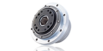
Next, and this can be additive to the first approach, is to use low-backlash devices built with extra precision designed to minimize gaps and compliance. Third, there are some forms of gearing that inherently have zero backlash such as found in precise cycloidal gearing and strain-wave gearing. This type of gearing is commonly used in robotics where precise positioning and quick moves is mandatory (see figure 3).
") There are tradeoffs with any approach. In the case of preloading, the spring load can accelerate wear as well introduce another possible point of failure. Modern CNC systems often use an additional motor and torque-balancing software in place of the spring to preload the second pinion, resulting in higher machine dynamics. Preloading also must be considered as part of the overall torque load budget for a gearbox. Adding preload detracts and limits the amount of torque the gearbox can transmit. Most important, mechanical solutions tend to be vulnerable to changes in the system introduced by wear and environmental swings.
There are tradeoffs with any approach. In the case of preloading, the spring load can accelerate wear as well introduce another possible point of failure. Modern CNC systems often use an additional motor and torque-balancing software in place of the spring to preload the second pinion, resulting in higher machine dynamics. Preloading also must be considered as part of the overall torque load budget for a gearbox. Adding preload detracts and limits the amount of torque the gearbox can transmit. Most important, mechanical solutions tend to be vulnerable to changes in the system introduced by wear and environmental swings.
When mechanical corrections are not possible, designers turn to electronic measures to reduce the oscillation and hunting. One common approach is to use closed-loop and an output encoder to close a position loop (see figure 4). This can be finessed by tuning the responsiveness of the closed control loops to reduce the velocities and acceleration of the machine. In the presence of excessive lost motion, using this input to drive the load to the desired position could cause the system to simply oscillate around the actual position, consuming power, wearing components, and introducing vibrations/buzz. Another problem with the closed-loop approach is that the lost motion persists, and will still delay proper positioning any time the load stops or reverses.
An alternative is to analyze the system to determine the amount of backlash and correct for it using an offset--adding/subtracting a small amount of additional motion to each path command at axis reversals (see figure 5). First, the motor is moved in small increments at low velocity and the amount of motion required to move the load is derived by comparing this value against the direct measurement.  adding an output encoder (left) allows the system to monitor the actual position of the load modifying the path commands tobdrive down error and place the load at the desired position. (Courtesy of Baldor Electric Co.)") To be relevant, data gathering must be performed with the position loop closed on the motor encoder. After this test, the system returns to a production state in which the position loop is closed on the direct encoder.
To be relevant, data gathering must be performed with the position loop closed on the motor encoder. After this test, the system returns to a production state in which the position loop is closed on the direct encoder.
Stiction
Stiction is another phenomenon that can impair the predicted motion of a system. Any two surfaces in contact display two coefficients of friction at the interface: the static coefficient of friction (stiction) and the sliding coefficient of friction. In this case, stiction is the holding force that must be overcome before the axis can begin to move. As a moving load decelerates to zero, stiction exerts a drag that can cause the load to stop short of its assigned position or even introduce a cogging motion if the drive is not tuned correctly.
Here, again, state-of-the-art technology can compensate for the problem. Each axis or component can be characterized to determine the amount of voltage required to overcome stiction. When an axis is at rest or decelerating, the controller modifies the commands handed down to the drive to give an extra boost to the axis. Even better, friction compensation can also assist in mitigating backlash, by helping the system more quickly compensate for lost motion after a stop or reversal. Stiction varies slowly, so it can be evaluated during integration/commissioning, then recalibrated weekly or monthly as required.
Increasing the integral gain while tuning the PID loop of the controller can help address stiction and backlash. It's an effective technique but it can be time-consuming, even when aided by analysis software. It's also important to note that for softer axes, the integral gain cannot be tuned as high. This only applies if an integrator is used in the position loop, and only for some applications. This method is rarely used in CNC systems, for example. In CNC systems, the position loops are generally tuned as aggressively as possible to address issues other than stiction. It is generally not possible to further increase the integral gain. When it comes to addressing stiction, acceleration-based friction compensation is a more typical approach.
 and direct encoder position with the position loop closed on the motor encoder (blue) show the deviation of actual position compared to commanded position, allowing the system to compensate for lost motion. Courtesy of Siemens Automation")
The key to managing backlash and stiction is to consider it from the very beginning. Understand the requirements and conditions of your application. Backlash and stiction don’t tend to be a problem for applications that focus on continuous speed, for example, or that only require coarse positioning of several degrees or greater. Before specifying components, seek as much information as possible about issues like stiction, based on your load, materials, etc. With the combination of best practices and today's technologies, you should be able to develop a system that will meet budget while delivering the performance you seek.
Acknowledgments
For useful conversations and technical review, thanks go to Matt Goska, Mechatronics Engineer at Siemens Automation (Elk Grove Village, Illinois); Bob Merrill,Product Manager for Servo Motors at Baldor Electric Co. (Fort Smith, Arkansas) A Member of the ABB Group; and Bob Mullins, Vice President of Sales, Harmonic Drive (Peabody, Massachusetts).
Motion Control & Motor Association
The Motion Control and Motor Association (MCMA) – the most trusted resource for motion control information, education, and events – has transformed into the Association for Advancing Automation.
Discover how Motion Control & Motor Association can support your automation journey with their complete range of solutions and expertise.
Visit Company WebsiteMotion Control & Motor Association 
The Motion Control and Motor Association (MCMA) – the most trusted resource for motion control information, education, and events – has transformed into the Association for Advancing Automation.
Harmonic Drive Introduces FHA-C-PR Actuator for High-precision Rotary Positioning
FHA-C Series low-profile, hollow shaft, brushless servo actuators are now available in 4 new models with 3 reduction ratios.