Industry Insights
Motion Control Spaces Out
 Vibration, vacuum, temperature extremes, and high radiation levels are just a few of the challenges space systems must overcome.
 Industrial environments can present significant challenges: heat, electronic noise, contamination, space limitations, and extreme performance or lifetime requirements. Such environments do offer one great advantage, however: They can be reached for maintenance. A servo motor not operating properly? Tune it. A drive fails? Put in a new one.
Space is nowhere near so forgiving. Launch exposes components to high vibration and temperatures. Once in orbit or beyond, they suffer vacuum conditions and temperatures as low as -160 deg C. Planetary and deep space missions must survive transit times of years, then face conditions like the heat and dust of Mars or the staggeringly high radiation levels of Jupiter. Above all, the specter of inaccessibility outside of Earth orbit hovers over the design process like a dark cloud. Building space systems is an entirely different proposition than producing machines for the industrial environment, but with careful design, motion control can rise to the occasion.
Up, Up, and Away
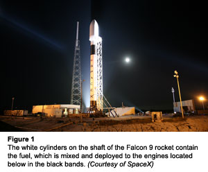
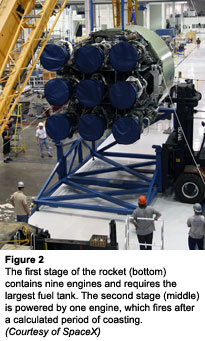
The role of motion control in space applications begins at the launch pad. Commercial launch vehicle specialist SpaceX (Hawthorne, California) uses servo motors to optimize the fuel mix in its Falcon 9 rocket engines (see figure 1). A two-stage design with nine engines in the first stage and one in the second stage, the rocket burns a highly refined form of kerosene known as RP-1, which requires oxygen as a catalyst (see figure 2). In the engines, pipes bring together the two fuels before the mix enters the combustion chamber. Although RP-1 does not require an exact amount of oxygen to burn successfully, the mix must be precise or else one or the other tank will empty prematurely, turning the leftover propellant in the other tank into velocity-killing ballast. The fuel-trim valve ensures that this does not happen.
The basic proportion of the fuel mixture is set by the diameters of the pipes from the individual tanks; the fuel-trim valve adjusts a small fraction of the flow to achieve even consumption. Each fuel-trim valve incorporates a butterfly valve driven directly by a servo motor based on double-closed-loop control. The outer loop adjusts valve angle while the inner loop maintains stable position in the face of launch stresses.
 And those launch stresses can be prodigious. In the first few minutes after launch, the engines produce 90,000 pounds of thrust. Not only is the adjacent fuel-trim valve subjected to shock and vibration, it is exposed to extreme temperature fluctuations between burn and the coasting period between stages. In fact, the single biggest challenge for the SpaceX engineering team wasn’t torque or speed or accuracy, it was finding a motor that would survive.
The team tested out motor after motor and finally chose to go with a 35-mm-diameter DC servo motor that provided over 40 mNm of torque. The engineering team paired that with a planetary gearhead to achieve a 159:1 reduction ratio. "They did a lot of testing with vibration fixtures to simulate launch conditions," says Gus Geil, Applications Engineer at MicroMo (Clearwater, Florida). "They eventually switched to a brushless motor and that really seemed to hold up."
Because the launch process is typically less than an hour long, including coast time, power consumption is not an issue, making the switch to brushless motors a worthwhile trade-off. To date, SpaceX has secured contracts for nearly twenty flights of its new Falcon 9 launch vehicle. While NASA remains SpaceX’s single largest customer, the company has commercial contracts with several international clients, bringing the promise of the commercial launch market closer to reality.
Rovers Are From Earth, Dust Is From Mars
The Mars Rover missions have placed three vehicles on the Martian surface: Sojourner, in 1997, and Spirit and Opportunity in 2003, all designed and built by the Jet Propulsion Laboratory (see figure 3). To traverse the rocky ground and steep slopes of the Martian terrain the six-wheeled vehicles required significant power-to-mass performance from their motors. Sojourner incorporated 25-mm-diameter, 20-W brushed DC Servo motors and 16-mm-diameter, 4.5-W motors. Spirit and Opportunity also used the 25-mm motors but added an additional 20-mm diameter, 4-W motor. Gearboxes further increased torque.
The components not only needed to survive the high vibration environments of launch, they had to arrive safely at Mars and perform once deployed on the planet's surface. Mars features a low-pressure, low-humidity environment with a high-carbon-dioxide atmosphere. Temperatures range from -133 deg C to 27 deg C. From the start, it was a challenge, says Jeff Randall, Sales Engineer at Maxon Motor (Framingham, Massachusetts). “There is one motor with one set of brushes for a task,” Randall says. “If the winding or the brushes or the ball bearings fail, motor is dead.” The JPL team performed extensive testing on brush materials before settling on a carbon-graphite-copper mixture designed to hold up to conditions.
Of course, no motor can function properly without lubrication. It is especially important for an application in which the equipment cannot be reached for maintenance. "The choice of lubricant is critical in these types of applications because if it is wrong for a specific environment it evaporates, and that will cause the motor to fail very quickly,” Randall observes. The team used Bray 601 wet lubricant, which operates over a temperature range from -100 deg C to +90 deg C, sufficient for the conditions that they faced. More important, the lubricant exhibits low vapor pressure, which prevents it from boiling away in a low-pressure environment.
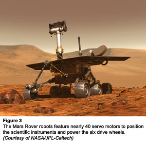 All the hard work paid off?the missions were a resounding success, exceeding all expectations. “They had specific lifetime requirements that they needed the motor to achieve,” Randall says. “Specification was 90 days, but JPL took the motors and engineered them in such a way that the Mars Rover lasted five years. It's really amazing what they've done.”
Jupiter Jaunt
Hard as it is to believe, the issues surmounted by the Mars Rovers look tame by comparison with the challenges of the Juno project. The Juno spacecraft will travel to Jupiter to map the planet’s magnetic and gravitational fields and atmosphere from polar orbit. Transit to the planet will take five years, followed by a one-year observational mission.
 Half the battle of building systems that will last is simply using good design principles, says Ray Head, Mechanism Designer at Lockheed Martin Space Systems (Denver, Colorado). “Make a mechanism that doesn't have a lot of sliding friction by using spur gears instead of worm gears, things of that nature,” he says. “Good lubrication is essential, as is material compatibility – for example, don't run 15-5 steel against 15-5 steel without some exotic lube or synergistic coating in between. We use a lot of nitronics 60 in these types of applications. Even if the lube is sparse there's no affinity for the materials to start to plate on each other. Things like that allow you to design a machine that will last.”
ROI Calculator

Discover the potential cost savings of robotic automation over a 20-year system life
This calculator compares your current manual labor costs against the total cost of owning and operating a robotic system over its 20-year lifespan.
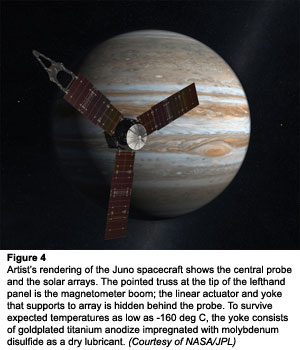
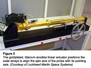
The Juno spacecraft design consists of a probe powered by a trio of solar panels arrayed at 120 deg around the spacecraft (see figure 4). They are supported by a lightweighted titanium-anodize truss that is goldplated to reduce emissivity to 0.03 and a yoke formed of a linear actuator with a 6.5-in stroke (see figure 5). The panels will be folded for launch, then released to passively deploy via a viscous damper. During transit, the system will correct slight wobbles in the spin of the spacecraft to coordinate the spin axis with the pointing axis by using the mass of the three solar panels. The system shifts panel position using the three actuators, which are driven by three-phase stepper motors with a 210:1 planetary gearhead. “One of its assets is the passive detent [holding torque],” says Head. “It's advantageous for very limited power.”
The ballscrew actuator translates another set of bearings that are separated from it by a flexure. Because the ballscrew is so far separated from the gear train, its motion is limited by the 672:1 reduction ratio for the actuator assembly. “We don't expect it to need to go the full stroke,” says Jon Taylor, Mechanism Designer at Lockheed Martin Space Systems. “It is going to be used roughly five times. We expect to have to adjust it after the solar arrays are deployed to tweak the spin axis of the spacecraft to the pointing axis. As fuel dissipates, the center of gravity might move so again we need to reposition the solar array to get that spin axis aligned with the pointing axis.” Linear potentiometers will provide feedback but the system is designed to operate open loop. A few of the parts see quite a few cycles but given the combination of the large gear train to leverage the passive detent, connecting to the ball bearing and small spur gear set up to do minimal work, the assembly should last a long time”
One of the challenges is heat variation across the assembly. The tip of the support structure for the sliding solar panel can drop as low as -160 deg C, while the drive portion of the assembly is thermally stabilized. The truss is coated with gold for low emissivity, and heaters and blankets cover the motion components to maintain it at the relatively high temperature of -60 deg C.
 Interestingly, given the absolute requirement for reliability, the assembly will be ground tested 12 times for a total of 17 cycles. To confirm that all that testing won’t wear out the flight unit, as well as to verify the design and identify defects, the group will put an identical qualification unit through lifetime testing of three times the number of total cycles expected from the flight unit. If the qualification unit can survive 51 cycles, the thinking goes, the flight unit should easily accommodate 17 cycles.
Covering Up
The other essential motion system operates the hinge of the main engine cover, which protects the main engine bell against micrometeorite impacts except when it is firing. If the cover failed, the mission would be severely compromised, so unlike the solar-panel positioner, the engine cover system features full redundancy. “It is essentially one stepper motor driving against another stepper motor,” says Taylor. Both stepper motors are fitted with gearheads for a whopping 1795:1 reduction ratio. “The active motor drives against the passive detent torque of the inactive motor,” he continues. “We essentially have a shaft in a shaft, with redundant sets of bearings, redundant motors, and redundant potentiometers. We’re fully redundant in every category you can think of, protected against every failure except just a straight up structural failure, which we don't worry about being redundant against.”
To minimize weight, the engine-cover stepper motors are 1.5-in. in diameter, 3- to 4-in long, and about 21 oz, while the linear-actuator motors are 1.25-in in diameter and weigh less than a pound. The motors are brushless, removing a point of failure for vacuum environments.
As with the Mars Rover vehicles, lubrication is critical. For wet lubricants in the temperature-stabilized portion of the craft, the team chose Penzane NYE 2001 and Bray 601 EF. “They may not be the slipperiest lubes in the world but they are very stable in a vacuum,” Head says. “Outgassing is a big problem. You can't have it plating on optics so you’ve got to be very vacuum safe. All glues, all polymers have to be baked out or meet the NASA standards.” On the portions of the spacecraft that will drop to -160 deg C, the team has impregnated the titanium anodize with molybdenum disulfide and run that sliding surface against other gold plated parts.
The final challenge is building a system that can survive not only solar radiation but the intensified levels found in the Jupiter orbit, which Head characterizes as being on the order of megarads rather than kilorads. Prolonged exposure can cause parts to become brittle or reduce insulation to powder. “There are failure modes associated with long exposure to intense radiation,” Head says. “Jupiter has got a terrible radiation problem. We had to build a big vault to make the electronics survive.” The problem is that mechanisms such as the linear actuator and the system that operates the engine cover cannot be place in the vault; they need to be on location and so must be designed with proper materials and lubricants to survive a radiation-hard environment. In part for this reason, Head avoids seals, instead choosing to work with labyrinth-type shields.
Slated for launch in August 2011, the Juno spacecraft is expected to reach Jupiter five years later and operate until October 2017. Like the Mars Rover teams, the Juno engineers at Lockheed Martin will do their best to design a system that can survive longer, but with the extreme environmental conditions, it remains unclear whether that is possible. Just meeting specifications would be a triumph in and of itself.
Space exploration presents some of the greatest possible challenges to motion control systems and the engineers who design them. Using the types of techniques described here, along with today’s ever tougher, more capable components, teams can rise to the occasion and help mankind learn more about our universe.
Acknowledgments
Thanks to Juerg Frefel of SpaceX for useful conversations.
Motion Control & Motor Association
The Motion Control and Motor Association (MCMA) – the most trusted resource for motion control information, education, and events – has transformed into the Association for Advancing Automation.
Discover how Motion Control & Motor Association can support your automation journey with their complete range of solutions and expertise.
Visit Company WebsiteMotion Control & Motor Association 
The Motion Control and Motor Association (MCMA) – the most trusted resource for motion control information, education, and events – has transformed into the Association for Advancing Automation.
Motion Control is Blowing in the Wind
Motion control technology tunes blade position, damps vibration, and keeps wind turbines turning for optimal power generation
Kollmorgen Presents AKMH Servomotors and AKD Decentralized Drives at Interpack 2014
Kollmorgen will be exhibiting its family of motion control solutions for packaging machine builders at Interpack 2014, located in Dusseldorf, Germany, from May 8-14, 2014
Design of Brushless Permanent-Magnet Machines
Brand new 822-page brushless machine design book written by J.R. Hendershot & T.J.E. Miller