Industry Insights
Motion Control Powers Defense
 Motion control performs a wide range of tasks in the military/aerospace market, often under conditions that place demanding constraints on the technology: extreme weather, electromagnetic interference (EMI), erratic or unavailable power and more. The bar to success may be high, and yet successful designs can accomplish jobs that are otherwise impossible or that take soldiers out of harm’s way.
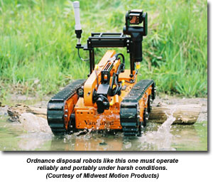
Midwest Motion Products LLC, or MMP, (Watertown, Minnesota), for example, produces closed-loop gear motors for the automated and unmanned vehicle markets, with a particular emphasis on portable ordinance disposal robots such as those used to destroy explosive devices or suspicious objects in places like Iraq.
Meeting Design Challenges
It’s not easy, of course. The desert environment is a harsh one, so part of the company’s design process has to focus on protecting the components from heat and dust. “Our standard units are IP [ingress protection] 54 rated,” says MMP president Randy Cordes. “We use gaskets in between the motor housing and end caps. We use sealed bearings, as well.” In a nod to the temperature constraints, they also work with a lubricant that’s designed to operate from -40 deg C to 140 deg C.
The robots can carry loads as heavy as 1000 pounds and travel as fast as 10 mph. Because the units are often battery operated, MMP must balance parameters such as output torque and speed with lifetime. They mix and match the combinations of windings and gear ratios to reduce the current consumed and maximize battery life.
In an effort to balance robustness with cost, the designs use brushed motors. “It’s not as though these are running at a factory 24/7,” Cordes says. “The duty cycle probably lasts minutes as compared to hours, especially considering the fact that they will require a charge. Brushless motors would simply add more cost and certainly more delicate drive electronics would be required.”
More delicate electronics would mean a more delicate system, and reliability is paramount in such an application. “They must not fail,” says Cordes, citing, for example, the gearhead pinion that is the sole point of power transfer from motor to gearhead. “If gearhead pinion happens to fail, you have a gear motor that does not have any output torque or speed.” To protect against this possibility, MMP not only pressfits bulk components together, it uses permanent adhesive, plus a set screw fixed in place with -- you guessed it -- more permanent adhesive. “We’ve basically got three levels of protection to make sure the part never fails,” Cordes says.
 All Helicopters On Deck
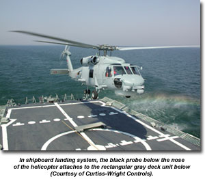
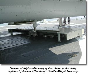
Reliability is also a top concern for Curtiss-Wright Controls Marine Defense (Mississauga, Ontario, Canada), which builds a shipboard helicopter landing system called the Aircraft Ship Integrated Secure and Traverse system (ASIST). In the ASIST, a telescoping probe lowers from the helicopter as it drops down to hover over the deck of the ship. On the deck, a winch controlled by a servo-driven hydraulic pump draws out a rapid securing device (RSD) that secures the aircraft. The RSD must maintain its position relative to the helicopter during the final landing sequence in order to complete capture -- no easy feat in rough seas.
The choice of hydraulics was pragmatic, given the torque and power requirements of the project. But hydraulics alone couldn’t do the job. “When we started looking into this project, we found that in order to get the kind of frequency response and control we needed, we had to use servo control,” says Jay Gandy, engineering manager, ASIST, at Curtiss-Wright Controls. The unit uses a servo-valve-controlled Denison pump to run the main traverse winch, which controls the position of the RSD.
Fine control capability is meaningless if you don’t have the data to issue control commands, though. The control system integrates speed and position feedback, captured in part from a machine vision system. Each aircraft carries a set of IR beacons. Cameras on the deck acquire and validate the beacons, then perform a geometric analysis to determine the correct location of the probe, all at about 30 Hz.
“We have a target discrimination algorithm that distinguishes the helicopter beacons from all the background images, so that's the most CPU-intensive portion of the software,” says software engineer Ken Kwon. “Our automatic RSD tracking control system and the vision system software are all on one processor board and actually tallying image data from two cameras, so there's quite a lot of processing on a single processor. We have to be pretty efficient and robust in our coding.” Among other things, they design the software so that it is all event driven -- it only runs when there's actually work to be done.
Harsh environments
Of course, that work has to be done in a wide range of conditions. The landing systems operate everywhere from southeast Asia, with its high humidity and condensation, to the Arctic, with its frigid temperatures. “We’re getting rained on and snowed on,” says Gandy. “We’re competing with the sun and reflections.” That means the target discrimination software has to be robust and reliable. “We’ve spent a lot of time and money over the years trying to find ways to optimize it, and then, of course, ways to make it less expensive,” he adds. The original system included several processor boards with a total of five processors; the current system requires only a single board.
The discussion of weather brings up the larger issue of environment. The ASIST unit has to survive shock loads on the order of 100 Gs and what Gandy characterizes as a “fairly severe” vibration regime. During testing, each unit is vibrated at its natural frequency for two hours to ensure that no elements shake loose. In addition to designing a system robust enough to withstand the humidity and the corrosive salt of the marine environment, the design team had to develop a system capable of withstanding electromagnetic pulses (EMPs) and high levels of electronic noise.
“The top side of the ship is bristling with radar sets and the radios are active,” says Gandy. “Everything in our system becomes an antenna, plus they don't want an emitter affecting other sensitive equipment on board the ship or degrading their level of stealth.”
All of it acts to both limit material choices and impose the need for additional protection. The team’s approach is to begin with industrial or aerospace components, then add the protection to enable them to survive the environment, as well as shielding and grounding to combat EMI and EMPs.
Aircraft Unit Design
The company also produces the aircraft component of a similar helicopter landing system known as the Recovery Assist, Secure and Traverse system (RAST). The helicopter probe must be lowered from inside the flooring of the aircraft by a winch, which then drops a cable to the deck to latch onto the RAST recovery assist cable. The winch is driven by a brushless DC motor and fitted with both a Hall effect sensor and a tachometer to provide feedback on speed and load.
 Of course, such a system is subject to the same sea environment as the ship-board system, but operating in the aerospace environment imposes an additional set of challenges. Weight, of course, is a key concern. “Invariably, on an aircraft you have very severe space and weight restrictions and so we had to shrink everything down into very, very tiny packages that still produced a fair bit of power,” says Gandy. “An additional challenge is that this equipment is sort of mounted on the belly of the aircraft underneath the floor and it turns out to be major surgery to ever get at it. I think we can get in to maintain it once every five years.”
Reliability, in other words, is critical, so much so that the reliability testing alone is a two-year effort. One part of the design approach was to build a custom controller that consists of a trio of circuit boards stacked up. “We basically had to go with customized integrated drives,” says Gandy. “The entire thing is packaged up on the winch with almost no cabling at all. It's all internal.” That includes accessories such as the EMI filters. The final product consists of a package 2 inches x 2 inches x 4 inches. A nice trick, considering a commercial unit that Curtiss Wright used for early tests measured 9 inches x 6 inches x 18 inches.
The team avoids the use of Ethernet for system-wide communication, says Kwon. “We do use Ethernet for some of our diagnostic tools but our products normally don’t use networking or a field bus for accessing our sensors,” he notes. “It’s a hardwired solution. All the processing is done within our system processor.”
“It has to do with the types of failure modes we have to have,” says Gandy, pointing to the shipboard power and interference issues already mentioned. “If we have a huge EMP surge that knocks out the central computer, we still need to be able to capture the helicopter. Historically that's driven us to solutions that don't look quite as modern as some of the technologies that are out there.”
And yet, in some ways they are right on the cutting edge, as with their use of absolute encoders on the shipboard part of the system. If power is lost in the middle of a capture operation, the last thing they want is for the encoders to rehome themselves on startup.
Defense applications may present strict operating and performance demands, but motion control technology can rise to the occasion through thoughtful engineering and careful choice of hardware and software.
Motion Control & Motor Association
The Motion Control and Motor Association (MCMA) – the most trusted resource for motion control information, education, and events – has transformed into the Association for Advancing Automation.
Discover how Motion Control & Motor Association can support your automation journey with their complete range of solutions and expertise.
Visit Company WebsiteMotion Control & Motor Association 
The Motion Control and Motor Association (MCMA) – the most trusted resource for motion control information, education, and events – has transformed into the Association for Advancing Automation.
Multi-Axis Linear Motion System Design & Control using LabVIEW 'Seminars' in October
Electromate is pleased to announce it will be hosting four Multi-Axis Linear Motion System Design & Control using LabVIEW Seminars in October in Toronto, London, Montreal & Quebec City.
Nexen Group Announces Partnership with Reliability Resources
Seattle-based Reliability Resources will provide expert coverage of Nexen products in the Pacific Northwest region.
Choose the Best Ethernet Cable For the Application
Sophisticated shielding and ruggedized connectors yield industrial Ethernet cables able to survive the factory environment.