Industry Insights
Linear Motors Part I: The Straight Scoop
 Although the most common servo motors are rotary, many problems in manufacturing, packaging, metrology and processing require motion in a straight line. One way to achieve linear motion is by fitting a rotary servo motor with a linear actuator -- a ball screw, for example, or planetary roller screw. Another way is to generate linear motion directly with a linear motor.
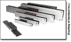
A linear motor is essentially a brushless rotary servo motor unrolled and laid flat. It features a set of coils contained in a forcer, which rides atop, or in some cases within, a magnet track. “Linear motors are three-phase motors like normal servo motors,” says Joseph Profeta, director of product management at Aerotech Inc. (Pittsburgh, Pennsylvania). “Electrically, if you were going to look at them on paper, you wouldn’t know the difference other than that the units might be in millimeters rather than degrees.” The coils are electrically commutated to generate magnetic fields that interact with the fields produced by the magnets to induce motion. Depending on the application, the forcer can ride over a stationary magnet track or, less commonly, the magnet track can ride over the forcer. A position sensor such as an encoder keeps track of location.
 Categorizing Linear Motors
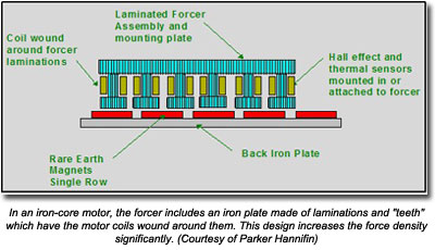
One way to classify linear motors is by the design of the forcer. In such a scheme, motors can be classed as iron core, laminated (also known as iron-backed), or air core (also called ironless). In an iron-core motor, the forcer is a slab of iron featuring additional prongs of iron projecting down. The coils are wound around these prongs, just as in some rotary servo motor designs. The iron improves coupling between the magnetic field of the coils and that of the magnets to increase the force generated by the motor.
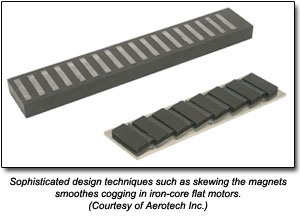
The drawback of the iron-core design is a phenomenon known as velocity ripple, or cogging. The magnet track of a linear motor consists of a series of magnets arranged end to end, north pole aligned to south pole. When the forcer travels along the magnet track, the velocity can be choppy as the forcer passes from pole to pole, as a result of the attraction between the forcer “teeth” and the magnetic fields. “Typically, as you move over the magnets, you’ll see a ripple due to those changes in the magnetic field,” says Profeta. “If you're trying to do very-high-precision motion with positioning and velocity regulation, those ripples may be too large relative to what you’re trying to position.”
A laminated or slotless design still includes the backing slab of iron but without the projections. It provides a compromise solution of a fair amount of force with smoother motion. A certain amount of cogging is inescapable, however. For precision applications such as semiconductor metrology, the best choice is an air core motor. 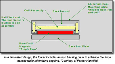
As the name suggests, an air core motor does not have iron projecting into the centers of the coils. In fact, an air core motor does not contain any iron at all; hence the alternate name of ironless. As a result, ironless designs tend to be almost free of cogging. “The benefit of ironless is that you don't have that attractive force between the forcer and the magnet rows,” says Ben Furnish, linear product manager at Parker Hannifin (Irwin, Pennsylvania). In other words, the motor isn’t fighting that attraction just to move the forcer along the magnet track. “Typically, with ironless motors you can also get higher speeds because you're moving less mass. They’re great for scanning applications where velocity ripple smoothness is important or highly dynamic applications.”
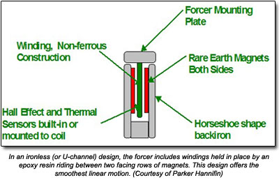 Another way to class linear motors is by the magnet configuration. The most common linear motors consist of a forcer riding over a flat magnet track. An alternative that provides very good force with smooth motion is the U-channel design, in which a forcer with an ‘I’ shaped cross section travels sandwiched between two facing rows of magnets. Although in theory a U-channel motor can be iron core or ironless, in reality, iron-core U-channel designs tend to be the exception rather than the rule.
The benefit of the U-channel design is that it has double the magnets, which increases the force generated, and thus the speed and acceleration. Of course, the downside of the U-channel design is that it has double the magnets, which significantly increases cost and weight. For certain high-performance applications, however, that’s a worthwhile tradeoff.
Choosing a Design
As with most aspects of motion control, which type of linear motor to use is driven by the requirements. In a low-precision automotive parts manufacturing application, for example, the added force and reduced cost of an iron-core motor may offer the best solution. In a nanoscale metrology application, however, a U-channel design is more likely to provide the desired smoothness.
“If velocity ripple or very accurate positioning is important, you might start looking at an ironless U-channel motor because there’s no cogging in those styles,” says Profeta. “In the iron-core motors, there's cogging, but you typically get a higher force per unit volume because you have a stronger coupling between the magnetic fields; therefore you can get a higher acceleration in a smaller space.” In manufacturing, conserving space is paramount, which can make laminated designs very attractive as a general solution.
With iron-core or laminated designs, some degree of cogging is inevitable. “You can skew the magnets at angles and skew the windings at angles,” says Furnish, “but you can never fully get away from the fact that you have that attractive force between the iron forcer and the magnet row.”
 Manufacturers work to minimize cogging with careful design of everything from magnets to coils. “It's not as simple as just taking a piece of steel and gluing a bunch of magnets onto it and saying okay, let’s throw some coils through there,” says Profeta. “The art goes into the selection of the magnets, the style, how large you make the magnets, how you wind and orient the coils to get the maximum flux path through the motor. Exactly how do you shape the coils, how do you overlap them, how many turns do you put in, do you use thinner or thicker wire, do you use less or more turns? That's part of the design process that any manufacturer would go through to create a forcer.”
Bearings Have a Bearing
Because linear motors provide direct motion without the mechanical windup of a screw, for example, they offer higher acceleration and speed than a motor/actuator combination. The forcer rides over or between the magnets but does not actually touch them, so the motors have no wear points. Put it all together and you get very precise positioning and velocity control, coupled with low maintenance and high reliability.
That’s the theory. In reality, most practical applications require a bearing of some sort to guide motion between forcer and magnet track and carry the load. This adds wear points, unless the device in question is an air bearing, in which case, you trade wear points for more complexity and higher cost.
Certainly, a mechanical bearing is economical and easy to install, but it means effectively reducing one of the advantages of a linear motor. At the same time, it still maintains fewer wear points than the rotary servo motor/actuator combo. “With a [ball-screw linear actuator], your lifetime may be limited by the screw thrust if it’s an application where you’ve got a lot of axial force, or the bearing load if your payload is the limiting factor,” says Furnish. “You’ve basically got two weak links. With a linear motor, you’ve got only the one weak link if you’re using the mechanical bearing, and that's the wearing of the bearing set.”
It’s important to size the bearings properly for a linear motor. The bearings have to do more than handle the load, they need overcome the attractive force between the forcer and the magnet track, especially for iron-core designs. “Where typically your payload may be 5 pounds, you may have to size your bearing for 500 pounds because of the attraction,” says Furnish. “That's what people who select just the linear motor components and then go size the bearing need to take into account.”
The Tradeoffs
If there’s one truism in engineering it’s that there are always tradeoffs. Unlike a rodless or rod-style linear actuator, linear motors are not self-supporting. They must be mounted to a surface, and not just any surface. Torsion, in particular, is a problem, at the very least reducing efficiency and at worst causing the forcer to bind up against the magnet track. The magnet track must be mounted to a very flat surface with high rigidity.
Heat is a perennial issue in motion control. In the case of the U-channel configuration, the motor can be mounted with the U facing down, which minimizes the entry of contamination into the magnet channel but also decreases heat transfer. For most applications, this is not an issue but if a linear motor is being used in nanoscale metrology, for example, it can be a problem. Fortunately, most such applications take place in cleanrooms, removing the need to make a choice between thermal management and contamination management.
In most cases, linear motors do a pretty good job of dissipating heat because the forcer moves along the magnet track which allows for constant convection. In addition, the mounting for the magnet track and the bearing on the forcer act as heat sinks.
The issue of thermal management does add another nuance to the comparison of iron-core and ironless designs. “With the iron-core designs you get better heat dissipation because the iron acts as a kind of a conduction source,” says Furnish. “Heat is really the issue with any motor -- the hotter the motor gets the less efficient it will be -- so you're typically going to need a much bigger ironless motor for the same type of forces as you would for an iron-core motor, not only because of the iron benefits of force but also because of the heat dissipation capabilities of the iron-core motor.”
There are other subtleties to consider. In all motors, the coils or windings generate heat. In a rotary motor/linear actuator combo, that heat is generally far away from the payload. In a linear motor, the heat is generated in the forcer, which generally carries the load. “The longer you operate, the higher the duty cycle, and heat conducts directly into the payload,” says Furnish. “If your payload is sensitive to thermal diffusion, then that’s definitely a concern. On a ball-screw-driven table, your payload is not going to see much delta in temperature because as the screw heats up it's not going to be significant enough to affect your payload. The linear motor is going to heat up right at the carriage surface, so that is another one of the things you need to consider about linear motor technologies.”
In part II of this article, we’ll take a closer look at the pros and cons of linear motors, examining when to use linear motors and when to look to linear actuators.
ROI Calculator

Discover the potential cost savings of robotic automation over a 20-year system life
This calculator compares your current manual labor costs against the total cost of owning and operating a robotic system over its 20-year lifespan.
Motion Control & Motor Association
The Motion Control and Motor Association (MCMA) – the most trusted resource for motion control information, education, and events – has transformed into the Association for Advancing Automation.
Discover how Motion Control & Motor Association can support your automation journey with their complete range of solutions and expertise.
Visit Company WebsiteMotion Control & Motor Association 
The Motion Control and Motor Association (MCMA) – the most trusted resource for motion control information, education, and events – has transformed into the Association for Advancing Automation.
Bosch Rexroth Celebrates 40 Years of Business in the U.S.
Bosch Rexroth Corporation marked 40 years of operation in the U.S. with an anniversary party September 21st at its industrial
Midwest Motion Products, Inc. - “IP-54” Sealed, Low Current, 24 Vdc Gearmotor
NEW 24 VOLT, 2.0 RPM DC GEARMOTOR “Powerful, Lightweight, Unit provides benefits for Solar Tracking, Turntables, Robotics & Automation Applications”