Industry Insights
How to Select the Right Encoder for Your Motion Axis
Feedback plays an essential role in motion control. Servomotors, and, increasingly, stepper motors leverage encoder feedback for precise control of both speed and position. An encoder is a transducer that converts the motion of an object being tracked, such as the motor shaft or load, into analog or digital output corresponding to speed or position. Encoders are effective feedback devices but only when properly specified for the application and conditions at hand. Here, we review the process for choosing optimal encoder, step-by-step.
Things to Know About the Application
Specifying an encoder starts with the needs of the application. Key factors to consider include:
- Environmental conditions, including temperatures, moisture, shock and vibration, contamination
- Type of motion: unidirectional or bidirectional, etc.
- Magnitude of the motion and sensitivity to rehoming
- Mechanical design, including compliance in the system
- Electrical requirements of drives and controllers
- Physical configuration, including form factor, physical distance between encoder and controllers
- Budget
Collect as much information as possible before reviewing models or calling your vendor – you want to make an informed decision.
I. What are the Environmental Characteristics?
The environmental conditions of the application drive the most fundamental encoder choice: type of sensor engine. The most common sensor engines are optical, magnetic, and inductive. Capacitive encoders do exist but they will not be covered in this tutorial.
Optical Encoders
How They Work: In an optical encoder, a patterned disc attached to the object being monitored (typically the motor shaft or the load) passes between a source (typically an LED) and a photodetector fixed to the body of the encoder (see Figure 1). The patterning of the disc either chops the beam to generate a train of square wave pulses or generates a binary digital word. In either case, the control/readout uses this data to determine position, and possibly speed. In a linear optical encoder, both source and detector move with the load while the linear scale that generates the output is fixed to the machine frame.
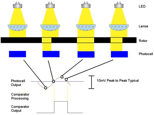
Figure 1: In an optical encoder, a patterned disc passes between a source and detector to modulate the beam. Onboard electronics process the output of the photodiodes to yield a square wave pulse train that can be converted to position and speed information. (Courtesy of SICK)
Pros: Optical encoders offer the highest resolution of this class of feedback devices. As such, they can be very good for scientific and demanding industrial applications that require tracking angular position to the order of fractions of degrees.
Cons: On the downside, optical encoders are sensitive to contamination and should not be used for applications exposing them to dust, moisture, or corrosive chemicals. Optical encoders with glass code discs are vulnerable to shock and vibration. These days, mylar code discs are more commonly used and more robust to a shock and vibration.
Best Used For: Scientific applications and industrial applications with very demanding output performance.
Magnetic Encoders
How They Work: Magnetic encoders operate analogously to optical encoders. Instead of optical code discs, magnetic rotary encoders use a different structure to perturb the magnetic field, such as a toothed ferrous metal gear, or drums or discs patterned with alternating magnetic domains; linear versions use linear scales. The alternating domains create a varying magnetic field that can be detected using any of several technologies, including simple magnetic pickups, or magneto restrictive detectors that offer better high-speed performance. Alternatively, the Hall-Effect sensor leverages a solid-state detector array that provides an economical, robust solution that combines high sensitivity and resolution with better tolerance of high shock loads.
Pros: Magnetic encoders can withstand extremely harsh conditions, making them good fits for industrial applications. They can operate under water, covered with dust, and exposed to very high vibration. They are quite economical, making them suitable for budget applications.
Cons: Sensitive to high magnetic fields and may require shielding. Very high shock loads can demagnetize the magnetic domains, as can very high temperatures; as mentioned, Hall-effect sensors are less vulnerable to shock loads. According to traditional thinking, magnetic encoders only provide moderate resolution. Once again, Hall-effect sensors provide improved performance. For demanding applications in extremely dirty environments, a Hall-effect sensor may be the ideal choice.
Best Used For: Industrial applications with harsh environments.
Inductive Encoders
How They Work: Inductive encoders are closely related to resolvers, which are differential transformers that determine absolute angular position of a rotating load by tracking the voltages induced in a pair of “readout” coils. The primary coil is attached to the rotor and energized, while the secondary sine and secondary cosine coils are attached to the stator. Rotation of the primary coil induces current in the secondary coils. Taking the arctangent of the ratio of the sine coil voltage and the cosine coil voltage yields the angle. Resolvers are extremely rugged but can be difficult to install. Inductive encoders were designed to address this drawback.
An inductive encoder is a solid-state implementation of a resolver. Instead of conventional coils, the coils are flat elements lithographically patterned onto a PCB (see Figure 2). All three coils are on the same PCB and mounted to the stator. A conductive disk mounted to the rotor or shaft excites the coils.
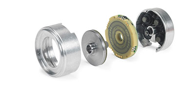
Figure 2: Exploded view of an inductive encoder shows lithographically patterned coils (second from right) and conductive disc (third from right). (Courtesy of Heidenhain)
Pros: Very high resolution. Robust to contamination, liquid ingress, extreme temperatures, and shock and vibration. Easier to use than resolvers and more compact, particularly eddy-current designs which use ironless thin films just 100 µm thick for the conductive disk.
Cons: Although the inductors are robust, the conductive disk can still create issues. Proper choice of the conductive disk is essential. Applications with thermal extremes should not use soft iron code discs. Ferrous or ferrite code discs may still be used in high magnetic fields but might require shielding.
Best Used For: applications with harsh conditions and high resolution/accuracy demands.
Can Your Application Handle Re-homing?
Encoders can be classed as incremental and absolute. Incremental encoders are electromechanical transducers that track incremental advances from some arbitrary home position set at start up. As a result, if they are shut down or fault out, they must be re-homed prior to operation (see Figure 3). For simple applications that just need speed control on a web processing line, for example in a package handling facility, an incremental encoder can be an economical solution.
Absolute encoders assign a unique digital word to each angular position. Because of this, the encoder can always return the angular position of the device being tracked when interrogated, even at start up. Best fits for absolute encoders include applications for which re-homing at any point in the cycle could result in damage or unsafe conditions. Examples include surgical robots, automotive robots, or interrelated mechanics or axes that could crash upon power up after a fault. In some cases, just the time spent rehoming can negatively impact productivity and justify the modest cost differential of an absolute encoder.

Figure 3: The code disk for an incremental encoder (left) is patterned in concentric zones of alternating opaque and transparent zones to generate a stream of square wave pulses. The disk for an absolute encoder (right) is patterned to generate a unique digital word for each angular position. Each bring in an absolute encoder tsk corresponds to one bit of resolution. (Courtesy of Dynapar)
What Are You Trying to Measure? Position? Speed? Direction?
For this question, we will start with incremental optical rotary encoders. (Note, incremental linear optical encoders operate analogously, as do linear and rotary incremental magnetic encoders.) The code disc of an incremental encoder is patterned with concentric zones, or channels, of closely spaced and evenly distributed lines that chop the optical beam as the disc turns. As a result, the photo current generated by the photodetector generates an analog pulse stream that gets digitized to create a square wave output representing pulses. Onboard electronics can convert the pulse stream into counts, but the the readout or control device must perform further processing to return position and/or speed.
If the system only needs to track unidirectional rotation or monitor speed, a code disc with one channel is sufficient. The problem is that the pulse stream from a single-channel encoder looks the same whether the disc is turning clockwise or counterclockwise. Applications that need to track direction require a quadrature encoder.
In a quadrature encoder, the code disc incorporates at least two channels, the A channel and the B channel. The two are patterned 90° out of phase. This returns two signals that are 90° out of phase electrically (in quadrature). As a result, channel A goes high first, enabling the system to detect direction of motion (see Figure 4).
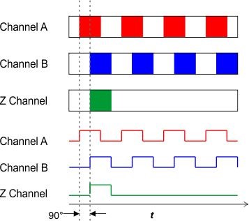
Figure 4: In a quadrature encoder, channel motors leads channel B by 90°. Because channel A goes high first, the system can always determine the direction of rotation.
Incremental encoders can also include channels for motor commutation, typically designated U and V. Although these may normally be of interest only to motor manufacturers, they could be useful for OEMs working with frameless motors.
Quadrature encoders typically also include a Z channel, a channel with a single pulse per revolution. The Z channel can be used for homing. It is also used to monitor multi-turn operation, iterating the reading by 360° each time the system reads out the index pulse.
As to the question of whether to go with a quadrature or a single-channel encoder, consider maximizing functionality. “The cost to add a full blown quadrature signal with complements and index is very little compared to just the cost of a standard say A pulse only,” says Jay Johnson, market product manager for motion control sensors at SICK (Minneapolis, Minnesota). “I'm always going to err on the side of caution and have all of those channels available to be used and read.”
Absolute encoders do not need special provision to track direction because each angular or linear position is assigned a specific digital word. They do, however, require a separate disc to monitor multi-turn operation. This disc interfaces with the primary disc using a simple gearing mechanism (see Figure 5).
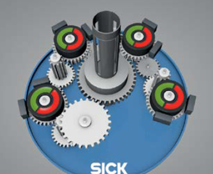
Figure 5: A multi-turn absolute encoder uses a simple gearing mechanism to tie the motion of the primary feedback disc with the secondary disc that monitors turns. (Courtesy of SICK).
How Much Resolution Do You Need?
Choice of resolution is probably the biggest pitfall in specifying an encoder. There’s a widespread assumption that a higher resolution encoder will automatically increase positioning accuracy. That’s not necessarily the case. The accuracy of any positioning system is limited by the mechanics. Even the highest resolution encoder will be ineffective if there is so much compliance in the system that it can’t reliably position to the accuracy required. “I think customers sometimes confuse the concepts, thinking that higher resolution means that their system is more accurate when actually it just means you can see more,” says Jonathan Dougherty, business development manager at Heidenhain(Schaumburg, Illinois).
In the best case scenario, extra money is wasted on the encoder and the system fails to meet positioning targets. In the worst-case scenario, the axis overshoots and moves back and forth, hunting for the commanded position but unable to reach it. This can delay operations or even cause the axis to fault out. In such a case, the money spent on the extra resolution might have been better applied to couplings with less compliance or shafts with less wind up.
To determine resolution, start by determining the smallest detection distance required by the application. Choosing a resolution that is about four times that minimum increment is a good rule of thumb. It could be boosted up to a factor of 10 for sensitive applications. Much higher than that will most likely be useful only in a handful of cases. “it seems like the default is to just go to the highest because they think it's better,” says Johnson. “Now, it might be in a really small percentage of applications but if you don't need it, it can do some damage. You're getting so much feedback that it just turns into noise and it could really induce problems in the system. So again, I look back for the practical. What's the smallest amount that I really need to be able to measure? As long as my resolution is four times that number, I am probably pretty good in the real world.”
Certified Motion Control Professional Program
Strengthen Your Skills and Enhance Your Career

Become a Certified Motion Control Professional (CMCP) and join the elite group of system integrators, machine builders, manufacturers, end-users and others recognized in the industry for their professional knowledge and expertise.
Rotary incremental encoders are specified in terms of pulses per revolution (PPR). This refers to the number of lines patterned on the code disc.linear incremental encoders are specified in terms of lines per unit length.
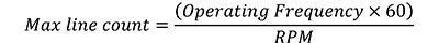
There is a wide difference between the resolution required for the application and the resolution that can actually be achieved in the real system. For a rotary incremental encoder, the angular speed of the application (RPM) and the electronics bandwidth, or operating frequency (hertz), control the number of pulses that can be transmitted by the hardware. We can calculate the resolution that is physically possible for a given an encoder using the following formula for maximum line count:
Operating frequency is internal to the encoder electronics. It is provided by the manufacturer, and is typically on the order of kilohertz or megahertz. If you need high resolution output for a high-speed system, look for an encoder with a faster operating frequency.
To simplify encoder selection, manufacturers provide data plots of resolution as a function of speed (see Figure 6). Again, these data plots are specific to a given encoder and make it possible to balance between speed and performance.
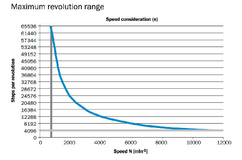
Figure 6: Plot of steps per revolution as a function of speed for a specific encoder makes it possible to balance operating conditions with performance.if the application can’t compromise on either speed or revolution, look for an encoder with a higher operating range or consider a different decoding scheme. (Courtesy of SICK)
Adding lines is not the only way to increase resolution. Resolution is a function of both PPR and how the signal from the photodetector is read out. The latter is referred to as decoding and depends upon what parts of the signal the system uses to trigger readout.
There are three formats typically used. Triggering off of the rising edge of channel A (1X decoding) provides a resolution equal to the PPR of the code disc (see Figure 7). Triggering off of the rising and falling edges of channel A (2X decoding) provides the actual resolution of twice the PPR. Triggering off the rising and falling edges of both channel A and channel B (4X decoding) gives a resolution quadruple that of the PPR. Depending on the application, it may be a good way to boost resolution with minimum additional cost. “You should consider the flexibility that you have, knowing that you can use a multiplier of 1X, 2X, or 4X to increase resolution through software implementation versus having to either buy new components or to purchase a new encoder with a higher PPR,” says Dalsen Ferrbert, applications engineer at Dynapar (Gurnee, Illinois).

Figure 7: Triggering on the rising edge of channel A (top) gives a resolution equal to the PPR of the disc. Triggering on the rising and falling edges of channel A (middle) doubles the resolution. Triggering on the rising and falling edges of both channels (bottom) increases resolution of the disc PPR by a factor of four.
That said, the approach involves trade-offs. For OEMs confident of the resolution they need, a higher actual resolution rather than one generated through software may be less prone to error. “Using interpolated pulse counts by counting the leading and trailing edges can work generally but it is important to be conscious of the quality of the square wave edges,” says Ferbert. “If you have longer cable runs, let's say 50 feet or more and you don't have the proper line driver, the signal edges are going to become less and less pronounced.” There are techniques that can be used to reduce noise over long cable runs. This involves properly specifying the output driver to screen out noise, which is a topic we will cover next.
What are the Electrical Requirements of Your System?
All the feedback data in the world will not benefit the system if it can’t be sent from the encoder to the readout device. Incremental and absolute encoders generate inherently different output, so their wiring and transmission schemes are different, as well. Incremental encoders require each channel to be wired directly to the control/counter device. There are two basic wiring approaches:
Single-Ended Wiring: One wire from each channel to the readout device, plus wires for Vcc and ground.
Pros: Less wiring, so reduces cost, complexity, points of failure, and opportunities for error.
Cons: Vulnerable to noise and loss
Best Used For: Very short cable runs in low-noise environments
Differential Wiring: Two wires (twisted-pair) from each channel to the readout device, plus wires for Vcc and ground.
Pros: Can be used for noise cancellation, extending cable runs and effectiveness in higher noise environments.
Cons: More wires, so increased cost, complexity, possibility for error, points of failure
Best Used For: Applications with high noise or long cable runs
Incremental encoders require output drivers to transmit the signal to the readout device. The choice of output driver should be driven by the requirements of the receiving device. What are the voltage requirements for your controller/drive? The voltage needs to be high enough to be read and strong enough to survive transmission across the network.
Output drivers can be divided into three classes: open collector, line driver, and push pull. It is essential that they be compatible with the other devices in the circuit to avoid damage.
Open-Collector Output Drivers
Open-collector output drivers are the most economical devices. They are considered sinking output devices, which means that they provide a ground for the circuit. They should be used with sourcing controllers and drives, which will provide current to them. When the switch is off, the signal level “floats.” When it is on, the signal is pulled low. Open-collector output drivers need a properly sized pull-up resistor to provide the correct output voltage to the control.
On the plus side, open-collector output drivers are simple and operate with a range of voltage requirements. On the downside, they are vulnerable to noise and can only handle low currents, which limits their distance. They are best used for short cable runs in low-noise environments.
Line Drivers
For longer, higher-noise environments, line drivers may be better solutions. Line drivers are considered sourcing output devices, which means they provide voltage to the circuit. They are the appropriate choice for sinking controllers. In general, they provide 0-5 V output, so the controller needs to be able to operate within that restriction.
One of the big benefits of a line driver is its noise cancellation capabilities. When wired with differential wiring, a line driver can send the complement (180° out of phase) to a channel. The channel output and its complement cancel but the noise remains. As a result, it can be removed from the output (see Figure 8).
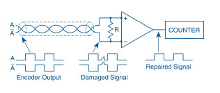
Figure 8: The differential line driver generates a complementary signal for each channel. Complementary signals cancel but the noise does not, making it possible to cancel noise and repair the signal. (Courtesy of Dynapar)
Push-Pull Drivers
The third type of output driver is the push-pull driver. This type can act as both a sourcing and a sinking driver, making a compatible with sinking and sourcing controllers, respectively. Push-pull drivers offer maximum flexibility and maximum transmission distance. On the downside, they are more expensive.
Because absolute encoders transmit digital words rather than analog signals, they offer a variety of different communications options. They include:
- Parallel Wiring: A pair of wires for each data bit. Parallel wiring sends each bit simultaneously but it does require more wires, which adds complexity and cost.
- Serial Interfaces: These hardware/software solutions send all bits over a single interface, one at a time. This reduces the amount of wiring required, cutting cost, complexity, and opportunities for error.
- Bus Connection: Fieldbuses such as CAN, Profibus, Modbus, etc., enable multiple devices to be linked through a master.
- Industrial Ethernet: Supports the connection of extremely high numbers of devices at very high speeds. Many protocols exist, including Ethernet/IP, EtherCAT, ProfiNET, DeviceNet, CANopen, IO LINK, etc.
What are Your Mechanical Requirements?
Before an encoder can provide feedback, it needs to be mechanically mounted on the system. There are multiple options available. Key factors to consider are: the space, the required form factor, and the mechanical performance of the motor shaft and load that will interface with the encoder.
Encoders can be classed as solid shaft or hollow shaft. Solid-shaft encoders must be coupled to the motor shaft or load. On the upside, couplings can be specified to compensate for run out and endplay of the motor shaft, reducing wear and tear on the bearing. On the downside, that compliance can also compromise the ability of the system to provide accurate feedback. Another drawback to shafted encoders is that they provide a path for current to pass through the encoder bearing and into the electronics.
Hollow-shaft encoders provide a method for addressing some of these issues. In a hollow-shaft encoder, the encoder shaft is not connected to the motor shaft. This eliminates the path for shaft current to damage the electronics.
Another important mechanical consideration is specifying the encoder bearing. Bearings are the most common points of failure for encoders and can impose speed restrictions. It’s essential to ensure that the bearing can handle not just the magnitude but the type of load. A radial load applies very different forces than an axial load, for example. Any applied load will impact performance and lifetime of the encoder, unless it is specifically sized for the task.
Depending on the application, a bearing-less encoder may be a better choice. Hollow-shaft encoders, in particular, lend themselves to bearing-less designs. In a bearing-less hollow-shaft encoder, the code-disc portion is attached to the rotating shaft of the motor while the static portion of the encoder is attached to the face of the motor. As a result, there is no need for a bearing in the encoder, which removes the point of failure and one of the primary restrictions on lifetime and encoder speed.
There are, however, trade-offs. Because the code disc is mounted to the rotating shaft, run out and endplay are directly transmitted to the encoder. As a result, mounting tolerances for run out and endplay become much tighter. It’s not a better option so much as a better option for the right application.
“It's kind of a give and take,” says Dougherty . “Do you go with the classical approach with the bearing? You will be able to handle shaft loads. Your motor run out and endplay can be a little less sensitive but you have to be concerned about top end speeds and need to ensure there are no shaft currents coming through. Bearing-less encoders are usually lower cost. You don't have to be concerned about shaft currents or high speeds. They usually have a longer life cycle but they're very sensitive to mounting tolerance, the runout, the end play, things like that.”
It’s important to note that not all hollow shaft encoders are bearing-less, nor do all shafted encoders include bearings (see Figure 9).
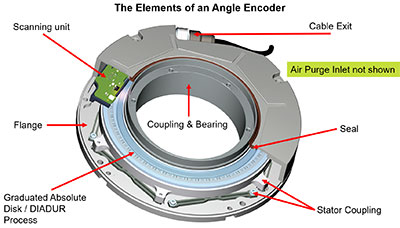
Figure 9: Hollow-shaft encoders include space for cabling or optical beams to travel. Hollow-shaft encoders may be bearing less or bearing style. (Courtesy of Heidenhain)
Encoder manufacturers offer a variety of mounting options, including face-mounting flanges, servo flanges, and square flanges for shafted encoders plus tethers for hollow-shaft versions. Making field modifications may seem like a good way to fit the encoder to the design. It’s an approach that can backfire, however, cautions London Rhodes, application engineer with Dynapar. “There’s a tendency for people to think they can just tap some holes or drill the encoder in, but this is one of those situations where it has to really be a precision mount,” he says. “Modifying to a mount that is not existing on the encoder is just not a good idea.”
Encoder specification is a process of trade-offs among numerous options. The application will determine whether the encoder needs to be rotary or linear, and incremental or absolute. The environmental conditions, resolution requirements, and budget will combine to determine the type of sensor engine to be used. It’s important to be strategic about specifying a resolution that will be beneficial and not detrimental to the performance and budget, alike. Let the electronic considerations determine wiring schemes and output drivers. Don’t forget about packaging and specialty requirements such as application-specific encoders and safety ratings. Finally, gather as much information as possible for your vendor prior to making the call. They have a deep well of experience on which to draw and can help you sift through your options to come up with the best solution for your system.
Acknowledgments
Thanks go to Kevin Kaufenberg, business development manager at Heidenhain, for useful conversations.
Motion Control & Motor Association
The Motion Control and Motor Association (MCMA) – the most trusted resource for motion control information, education, and events – has transformed into the Association for Advancing Automation.
Discover how Motion Control & Motor Association can support your automation journey with their complete range of solutions and expertise.
Visit Company WebsiteMotion Control & Motor Association 
The Motion Control and Motor Association (MCMA) – the most trusted resource for motion control information, education, and events – has transformed into the Association for Advancing Automation.
Maxon Showcases Five Powerful Compact Drives At SPS 2022
Maxon is launching five new products at the upcoming SPS trade fair in Nuremberg.
US Digital E4T Mini Optical Encoder
The E4T Mini Optical Kit Encoder is one of our most popular encoders. It comes in resolutions ranging from 100-1,000 CPR and supports 11 shaft sizes, ranging from 2mm to 1/4".