Industry Insights
Robotic Transporters for Large Weldments
Robotic transporters are key when you want to automate welding of extremely large, heavy parts. The maximum work envelope radius of an extended-reach robot is about 3-meters (9.84’). If the parts you are welding require more reach than that, you need to find ways to move the robot to the part to provide optimal torch access to the welds. A variety of robot transporters are available, and each type lends itself to a particular type of work flow. How do you decide whether your application is best-suited for a linear floor- or wall-mounted track, linear overhead gantry or radial transport beam solution?
Factors to Consider When Choosing a Robotic Transporter
* Cost. Of course, cost is always one of the biggest factors to consider when selecting a robot transporter configuration. A single robot costs less than a robot combined with a transporter. However, a robot on a transporter can reduce the need for additional robots and maximize the use of your capital equipment investment. Multiple robots can be used together on some types of transporters to improve productivity. Certain types of transporters take up more floorspace, while others reduce floorspace needs. Some have expensive installation requirements, while others have facility and structural limitations or require special accommodations for part handling.
* Part Size and Configuration. You will need to know the physical dimensions (length, width and depth) of all of the parts you wish to weld robotically. Does the part need welds on all sides, on the outside only or does the robot also have to reach inside the part? Also, are short, intermittent welds required or does the part call for continuous welds along its length? In the case of tubular parts, are the welds circumferential?
* Part Flow. Do the parts flow in an inline production configuration or do they enter the workcell from opposing sides? Are work stations parallel (next to each other) or opposing (on opposite sides of the robot)? Are parts loaded using an overhead crane, by forklift or via some other method?
* Facility Structural Considerations. These include floor reinforcement (thickness of concrete) needed to support the robots and transporters, aisle width, ceiling height, support column spacing, overhead cranes, and other things like lighting and ductwork with potential to cause interference with the robots or transport structures.
* Safeguarding Considerations. Worker safety is very important in any manufacturing plant. Safety equipment generally is designed to comply with the ANSI/RIA 15.06-1999 safety standard. Welding cells require perimeter guarding with arc flash protection curtains; personnel gates with safety interlocks; and light curtains at operator workstations and any pass-through openings to the welding cell. Transporters may require limiting devices to be used as interlocks for safeguarding the work space.
 * Production Requirements. You will need to determine whether multiple robots will be needed to meet required production volumes. Calculations need to be based on the number, length and type of welds (single or multi-pass) required per part. If these calculations show that multiple robots will be required, you need to decide whether the robots need to share the same workspace (overlapping envelopes) or separate, adjacent tracks will suffice.
Types of Robot Transporters
Linear Floor Tracks – Generally the least expensive robot transport option, linear floor tracks allow the robot to reach welds on very long parts. Tracks can be up to 30 meters (98.4’) long -- length is limited by the manipulator cables. One or more robots are mounted on a carriage that either indexes between two or more fixed positions along the track length or is servo-controlled by the robot controller, which allows continuous positioning of the robot anywhere along the length of the track.
Usually, if the robot needs to move to more than a few positions along the track, a servo-controlled track is less expensive. Servo-controlled tracks also provide more programming flexibility. With a servo-controlled track, the robot can weld a continuous bead the length of the track. Using coordinated motion control, the robot can even weld the part while it is turning.
A robot on a linear track can only access the part from a single side. The width and depth of parts that can be processed is limited to the reach of the robot arm. However, robots are often mounted on risers on the track carriage to increase their elevation and depth of reach.
Floor tracks take up a significant amount of floor space, but parts can be processed on both sides of the track (opposing work stations). Work flow is flexible. The cell layout can be configured to allow parts to enter from both sides of the track or move in and out in a straight line from multiple (parallel) work stations on one side of a longer-length track.
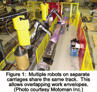
Anti-collision software enables multiple carriages to travel on the same track without interference. Carriages can also be expanded to allow two robots to be mounted on a single platform. Separate carriages are advantageous when relatively few welds are spread out along the length of the part. The robots can operate independently and work on opposite ends of the part or can be used to simultaneously weld along the same seam. Two robots on a single carriage saves the cost of an additional axis, and is suited for applications where multiple welds are grouped together. The carriage can be moved to a fixed position and the robots can then sequence the welds within their reach.
For welding applications, the carriage should be large and heavy enough to support a bulk wire drum. This greatly reduces wire feed issues. Trying to feed wire through conduit in a cable tray is less reliable and generally requires an assist feeder at the drum, which increases system complexity, cost, and maintenance issues.
Safeguarding a linear track is not too difficult if the manufacturer has provisions for mounting switches and cams to monitor the carriage position along the track. This monitoring might involve continuous position sensing or segmenting the travel into zones, depending on the risk assessment.
Floor tracks require leveling when installed, but work with modest concrete floor requirements and have minimal height requirements.
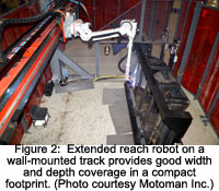 Wall-mounted tracks – Mounting a linear track in an elevated vertical position allows a robot to work from overhead. The robot can reach wider parts and can also reach down into part cavities. The design is slightly different from floor tracks and support columns for wall-mounting add expense. A robot on a wall-mounted track can only process parts directly in front of it, so this configuration lends itself to an inline part flow. The wall-mounted track can create a narrower workcell because parts are processed from one side and equipment can be located under the support structure. Care must be taken to allow for overhead clearance for the track and the rear of the robot on the carriage. Welding electrode delivery is more difficult with a wall-mounted track because the elevated rail is less conducive to mounting the wire spool on the carriage. Like floor tracks, multiple carriages can be located on a single wall-mounted rail. Limiting devices can be mounted to the robot arm to mute safeguards while the robot is overhead and become active when it moves down into a workstation. Like floor tracks, safeguarding switches can also be added to sense the carriage position.
ROI Calculator

Discover the potential cost savings of robotic automation over a 20-year system life
This calculator compares your current manual labor costs against the total cost of owning and operating a robotic system over its 20-year lifespan.
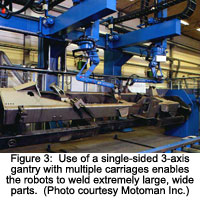 Linear Gantries – Gantries extend the envelop of the robot beyond the reach of a wall-mounted track by suspending the robot overhead and adding additional axes. A Y-axis of travel allows a wider part to be accessed by providing motion perpendicular to the length of travel. A vertical Z-axis allows a robot to reach deeper into part cavities. With the addition of gantry axes, a shorter-reach robot can be used to reduce the weight requirement for the gantry drives. Gantries with shorter axes can be supported from one side on a single rail. Larger span gantries utilize a bridge structure with supports on each side.
Driving a bridge gantry requires special robot controller software to synchronize the motion of two independent motors to position each leg of the gantry.
Gantries can add a great deal of expense to a robot system, but they are one of the few ways to process very large parts.
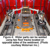 Utilizing two floor tracks on either side of a large part may be less expensive than a using a single robot on an overhead gantry. Multiple arcs afforded by the dual track configuration can enhance productivity.
A part positioner is normally combined with a gantry to turn the part for robot access. Most robots feature software which allows the coordination of all axes (robot, base, and positioner) to achieve long continuous welds or circumferential welds in a single pass. A sufficient Z-axis stroke can allow the robot to weld the inside truck bodies, containers or other box-like parts while a longer Y-axis could allow the robot to work on the outside surfaces. Of course, the longer the spans, the bigger the supporting structure and the higher the cost.
Long cable length and cable management become an issue the longer the stroke of the robot transporter. For gantry systems, it is not uncommon to mount the robot controller and process equipment to the gantry structure so only primary power is supplied the length of the track and the robot and process cables are limited to the Y- and Z-axis stokes. The other serious concern for a gantry system is overhead clearance, particularly one with a Z-axis stroke. Large parts normally require overhead cranes to load/unload. Users may want to add interlocks between the robot gantry and overhead crane to keep the crane out of the gantry area while the robot is operating or while the Z-stroke extends up in the air.
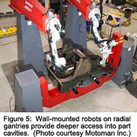 Radial Gantries – Radial gantries provide one of the most economical overhead robot transporter solutions. A rotary base is less expensive than a linear axis, but it has a fixed boom length. However, a single robot mounted on a two- to three-meter boom can expand its working volume by close to 10 times. Robots can be wall-mounted or ceiling-mounted on the end of the gantry boom. Wall-mounted robots provide a deeper envelope, allowing robots to reach into part cavities or access vertical surfaces, like the outside of a box. Ceiling-mounted robots provide a wide, flat envelope that is suited to processing flat panels such as mower decks or truck sides. Care should be taken that wire feeders or cables on ceiling-mounted robots do not hang down below the arm so they do not contact or snag the part or fixturing.
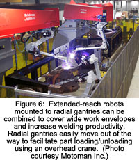
Like linear gantries, part positioners are usually combined with radial gantries to improve their flexibility. However, the orientation of the positioner in the workcell affects the robot’s access to the part. Locating a headstock/tailstock positioner perpendicular to the boom allows the robot to process longer parts using the length of the boom to move the robot closer to the headstock or tailstock. The width of the part is basically limited to the reach of the robot (nearly double the reach for ceiling-mounted robots), and part depth that can be accessed is limited. If the headstock/tailstock positioner is located so it is in line with the gantry boom, then the boom can be pivoted to either side of the positioner to allow the robot to access the part from each side, providing more depth. The boom length is fixed, so the robot can only access parts limited in length to approximately twice the robot’s reach. Booms can easily be moved out of the way to improve overhead crane access for loading and unloading large parts.
 Multiple carriages are not possible with radial gantries, but it is possible to combine multiple gantries in the same workcell. This enlarges the part envelop that can reached and adds multiple arcs. Radial gantries do not lend themselves to inline processing. Normally two work stations are located on either side of the base, 180 degrees apart. Limiting devices can be integrated to the boom axis to interlock to safeguarding in either work station and prevent overhead crane intrusion into the active workstation. Smaller robots can be mounted to a radial gantry to enhance their reach at a reduced cost. Radial gantries can be scaled up to include large extended-reach robots.
Because a radial gantry supports the robot as a cantilevered load, it must be rigid and have a solid foundation. Special foundation requirements, ballast or base plates may be needed to counteract the forces of a moving robot at the end of the boom. Utilities are normally routed through the interior of the boom, and welding wire benefits from the addition of an assist feeder mounted to the wire drum at the base of the structure. Process equipment, like nozzle cleaners, may benefit from being mounted on the boom in close proximity to the robot.
Radial gantries are often used in applications where short, intermittent welds or processing is done across the part, while linear tracks are often applied to applications requiring long, continuous weld seams. While coordinated motion between the robot, boom, and positioner is often possible to achieve continuous welds, it is more common to “park” the boom in a stationary position and move the robot to weld joints within its reach.
Summary
In summary, the dimensions of the part will generally dictate the method of transporting the robot. In some cases, two radial gantries or floor tracks might be more economical than a single multi-axis gantry solution. Utilizing extended-reach robots on a single-axis transporter is less expensive than multi-axis transporter solutions. If multiple robots are used in the same workspace, then programming and safeguarding for them must be addressed. It is most cost-effective to perform as much welding as possible on subassemblies in smaller cells, and limit the welding time of bigger components in large workcells to maximize their throughput.
Editor’s Note:
The article’s author, Chris Anderson, Technology Leader – Welding, Motoman Inc., welcomes questions and comments at 937-847-3216 or email to [email protected]. For more information and content related to Arc or Spot Welding, visit Robotics Online, Technical Papers.
Yaskawa America, Inc.
Founded in 1989, Yaskawa Motoman is a leading robotics company in the Americas. With over 600,000 Motoman robots installed globally, Yaskawa provides automation products and solutions for virtually every industry and robotic application.
Discover how Yaskawa America, Inc. can support your automation journey with their complete range of solutions and expertise.
Visit Company Website
Founded in 1989, Yaskawa Motoman is a leading robotics company in the Americas. With over 600,000 Motoman robots installed globally, Yaskawa provides automation products and solutions for virtually every industry and robotic application.